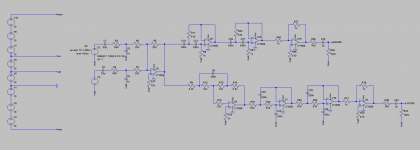
In the attached case all audio should be on the potential 'Vref'.
Would it work like this?
Should the amps and the preamp be isolated / decoupled from each other?
My thought is that they might influence each other via energy impulses they suck out of the batteries.
Those class d amps seem to be very sensitive about 'clean' DC-supply.
Would it work like this?
Should the amps and the preamp be isolated / decoupled from each other?
My thought is that they might influence each other via energy impulses they suck out of the batteries.
Those class d amps seem to be very sensitive about 'clean' DC-supply.
Attachments
I don't get it completely.
I plan to use them in series with a center tap which would give something around +-50V if fully charged.
Correct

That center tap will connect to the audio GND of the source.
Yes, that's correct.
I need the same center tap for the preamp, right? (then with the next possible potentials for +-12V (~13V))
This is where you have to make a choice.
Your preamp as drawn MUST run on its own separate supply because of the way you have it configured. That can be either two 9 volt batteries connected in series such that they apply 18 volts to the circuit as drawn. No centre tap is used. The lower battery negative is preamp ground and this would connect to the power amp ground. Power amp and preamp are treated as totally separate units.
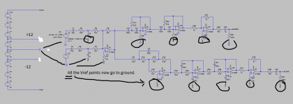
You could also feed the preamp from two series 9 volt batteries but this time use the centre point as ground. You would then need to alter the preamp so that all inputs and outputs were referred to this point.
Carrying on from the above, you then have the option to use the SLA batteries to directly power the preamp.
Like this.
Ok.
As far as i see we expressed pretty much the same with our drawings.
We only used different symbols and of course your diagram requires the opamp supply pins connected to '+12' and '-12'.
Pros and cons of the different methods are quite clear to me now....now i have to decide...
I still have my concerns about the wiring of the batteries, especially with a seperated ps for the preamp.
As it is i have audio GND from the source connected to the '-' of the 32V supply.
This should be connected to the center tap of the +-50V supply.
And via the power amp module that is connected to the negative pole of the speaker.
Does it really work like this?
Those high pass filters look a little severe! I think they work out to about 300+Hz at a guess. Why do you need all those stages?
What you seem to want is a simple volume control, for your laptop, no?
Any help is highly appreciated.
I have no laptop.
What shall i do?
It is an active xo for a woofer and tweeter horn.
2.2kHz, 24db.
I built one half of a baxandall tone control in the channel of the woofer.
It is battery powered and a pure mono system and uses a two channel amplifier for 'high' and 'low'.
In the beginning of the thread you see can see things than that.
This here works and that itself is quite a success for me.
I always like to hear about possible improvements (as a noob it is sometimes hard to catch attention, maybe because unappealing projects or asking the wrong questions ... hard to say from my viewpoint).
Atm i try to understand how i could implement a preamp like this into a system that uses dual voltage for its power amps......
you can use any of the slopes for the crossover.
single pole as in Butterworth, or Bessel, or somewhere in between.
or you can go steeper using 2pole. 2pole is easy with an opamp (discrete, or IC).
B2 and Bessel 2, or LR2 all work.
You can even mix single pole with 2pole on either half of the crossover.
You can go steeper still: 3pole, or 4pole.
B4, LR4 or Bessel 4 and lots of others over that range. Again you can mix.
One of the easiest 4pole is LR4. It is two B2 cascaded and uses just two opamps (one dual).
The two LR crossovers are probably the most common for audio.
I used LR4 for the jFET crossover using lsk170. The whole filter LR4 High Pass and LR4 Low Pass fits onto just over 1 square inch of protoboard. Power comes through an RCRC filter from the power amp supply rails.
Last edited:
I still have my concerns about the wiring of the batteries, especially with a seperated ps for the preamp.
As it is i have audio GND from the source connected to the '-' of the 32V supply.
This should be connected to the center tap of the +-50V supply.
And via the power amp module that is connected to the negative pole of the speaker.
Does it really work like this?
Yes, it really works like that.
The seperated ps for the preamp is the important bit here. Separate means its not referenced to any other item in the chain and that means it can be connected as you wish.
If you are using a Baxandall bass control on the LF side of the XO why not use it's inversion to your advantage and design it as a 12dB/octave crossover?
If you have a +-50V supply then there's no need to bother with single supply. A couple of Zener shunt regulators would be a simple solution for an op-amp based project.
If you have a +-50V supply then there's no need to bother with single supply. A couple of Zener shunt regulators would be a simple solution for an op-amp based project.
Excuse me mooly that i'm stressing your helpfulness.
I like to be save with this project, because of the quite high voltage and the possibility of very high currents going the wrong route .... destroying equipment, health, causing fire or whatever ....
Anything involving SLA's or any type of rechargeable battery should always be fuse protected in all the lines coming from the batteries.
If you are using a Baxandall bass control on the LF side of the XO why not use it's inversion to your advantage and design it as a 12dB/octave crossover?
The tone control part of the thing is meant as kind of a 'bass boost'.
The amplifier distorts heavily when this is used at higher volumes.
But at low volumes this allows for some extra 'boom'.
It is used outdoors, so any bit of bass is welcome.
I use 24db slope simply because it sounded best to me with the speakers i use.
I tried different filter types, but i experienced this to sound good.
I have no idea how to use that tone control as an crossover.
One reason to not have it in the signal chain towards the high sensitivity tweeter was that it causes to much noise.
Mooly showed me that in a simulation and the actual build of the newer version without 'treble control' showed much less audible noise from the tweeter.
If you have a +-50V supply then there's no need to bother with single supply. A couple of Zener shunt regulators would be a simple solution for an op-amp based project.
The only reason for single supply is that i have built some preamps previously with single supply.
Atm i like the idea of using 9V batteries, as this makes the whole preamp section more independent from the power amps.
Two (or four) of them with a center tap is the obvious solution, but i like the idea of using three of them and keep the preamp as it is (for now).
Can you explain the method you suggest?
Maybe that is an even better solution...
Anything involving SLA's or any type of rechargeable battery should always be fuse protected in all the lines coming from the batteries.
Ok.
I'm holding back an order of parts, until i know about everything i need.
Fuses are on the list.
What I think you should do:
Input Buffer - 2nd Order Bessel High Pass Filter - Tweeter Amplifier
- Baxandall Bass Control - 2nd Order Bessel Low Pass Filter - Woofer Amplifier
You can do this using only 4 op-amps which means power consumption is low enough to use zener regulators straight off the +-50V rails.
Input Buffer - 2nd Order Bessel High Pass Filter - Tweeter Amplifier
- Baxandall Bass Control - 2nd Order Bessel Low Pass Filter - Woofer Amplifier
You can do this using only 4 op-amps which means power consumption is low enough to use zener regulators straight off the +-50V rails.
- Status
- This old topic is closed. If you want to reopen this topic, contact a moderator using the "Report Post" button.
- Home
- Source & Line
- Analog Line Level
- Designing a noob-preamp (single supply)