So, silly question I feel embarassed for asking.
Disclaimer: I know virtually nothing about audio electronics, but I've built several microcontroller circuits and am more a software guy.
Application: I've made an arduino-based preamp/source selector with a darlington array and relays for source selection, opa2134 as unity gain buffer amp, pga2311 for volume control, lcd/rotary encoder for display/input. Damn thing worked first time out; very pleased. Maybe not audiophile quality but I gave up being an audiophile after several years flying helicopters.
Less pleasing: some hum I attribute to ground loops, you can hear every "click" the rotary encoder makes, and when the relays cycle to switch sources, even though I tell the PGA2311 to mute first, it makes a thump like God is knocking and he wants in BAD.
I attribute this to bad grounding, since I just tied everything vaguely marked "ground" together. For the first revision, I tried to clean that up, and then I realized I don't know how op-amp unity gain buffers really work.
I'm using the OPA2314 in a naive unity gain buffer config, just tying "OUT" to "-IN". I'm using an IA0505S to convert the circuit's +5/GND to +5/-5 for the op-amp.
And I finally noticed that no part of the op-amp circuit references either the signal ground or the supply ground. The input is "V+", but it's in reference to what? How does the signal ground come into play? Should I pin the "0V Out" on the IA0505S to audio ground? Can I ditch the IA0505S completely and do some mojo to supply the rest of the circuit's +5/GND to the supply lines and somehow call that good? I've read the "Audio Component Grounding and Interconnecting" page and I'm not much closer to figuring out how to keep this relatively quiet and still as bog-simple as possible ("simple" is more important than "audiophile"--remember, recovering helo guy).
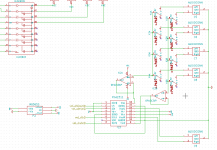
Sorry to ask something so basic, but I've done a lot of reading and it's still not clear. The relevant part of the schematic is attached; feel free to critique as I have little idea what I'm doing but can't seem to learn unless I fail repeatedly.
Disclaimer: I know virtually nothing about audio electronics, but I've built several microcontroller circuits and am more a software guy.
Application: I've made an arduino-based preamp/source selector with a darlington array and relays for source selection, opa2134 as unity gain buffer amp, pga2311 for volume control, lcd/rotary encoder for display/input. Damn thing worked first time out; very pleased. Maybe not audiophile quality but I gave up being an audiophile after several years flying helicopters.
Less pleasing: some hum I attribute to ground loops, you can hear every "click" the rotary encoder makes, and when the relays cycle to switch sources, even though I tell the PGA2311 to mute first, it makes a thump like God is knocking and he wants in BAD.
I attribute this to bad grounding, since I just tied everything vaguely marked "ground" together. For the first revision, I tried to clean that up, and then I realized I don't know how op-amp unity gain buffers really work.
I'm using the OPA2314 in a naive unity gain buffer config, just tying "OUT" to "-IN". I'm using an IA0505S to convert the circuit's +5/GND to +5/-5 for the op-amp.
And I finally noticed that no part of the op-amp circuit references either the signal ground or the supply ground. The input is "V+", but it's in reference to what? How does the signal ground come into play? Should I pin the "0V Out" on the IA0505S to audio ground? Can I ditch the IA0505S completely and do some mojo to supply the rest of the circuit's +5/GND to the supply lines and somehow call that good? I've read the "Audio Component Grounding and Interconnecting" page and I'm not much closer to figuring out how to keep this relatively quiet and still as bog-simple as possible ("simple" is more important than "audiophile"--remember, recovering helo guy).
Sorry to ask something so basic, but I've done a lot of reading and it's still not clear. The relevant part of the schematic is attached; feel free to critique as I have little idea what I'm doing but can't seem to learn unless I fail repeatedly.
Attachments
Add a 100K resistor from the non-inverting (+) input of each op-amp to ground, that should take care of a large part of the popping since it provides a dc path for the op-amp input regardless of whether anything is connected to it or not. (Op-amp inputs should not be allowed to float under any circumstances, there needs to be a path for input currents to flow.)
Make sure you have a set of bypass capacitors directly on the op-amp power pins to ground - 0.1uF film caps will be adequate.
I'd also recommend 47 ohms in series with the output of each op-amp (resistor right at the op-amp) to isolate board/wiring capacitance from the outputs for stability.
Make sure that the board's digital ground is connected to the audio ground at just one point.
+/-5V rails strikes me as very low for analog audio applications. I see the PGA2311 is designed for 5V rails so it seems unlikely this device is designed to switch redbook CD levels as linearity isn't going to be great with just a couple of volts of headroom - but this is more true with the op-amps which have neither rail to rail inputs or outputs. (OPA2134 assumed) I would add a pad in front of the op-amps if you run into clipping or distortion problems. I would probably change the op-amps to something with better low voltage performance.
Thanks for the inputs! Not the first time floating inputs have flustered me; I'll fix it (and the other items you mentioned). Really tremendously helpful.
Little surprised at your "+/-5v may not be enough"; I'll have a think. Since the microprocessor runs at 5v, I'm inclined to keep the supply voltage to everything at 5v as long as possible for simplicity, but in the long run the thing is likely to be fed by the 22v (ish) line running to my power amp (gainclone with simple transformer power supply... and similar grounding issues). So I'll have more voltage to play with if I need it.
Still... I thought line level voltages were pretty darn low, so the +/- 5v would be enough for a unity-gain amp. If it's just a quality-of-sound issue, I may not notice enough for it to be worth doing.
And I'm still confused... what's the + input on the op-amp in relation to, and how does the op-amp know that?
Thanks much--really really helpful.
Good advice, kevinkr.
The opamps are reference through their supply connections to ground.
...
And I'm still confused... what's the + input on the op-amp in relation to, and how does the op-amp know that?
...
The opamps are reference through their supply connections to ground.
Last edited:
Little surprised at your "+/-5v may not be enough"; I'll have a think. Since the microprocessor runs at 5v, I'm inclined to keep the supply voltage to everything at 5v as long as possible for simplicity, but in the long run the thing is likely to be fed by the 22v (ish) line running to my power amp (gainclone with simple transformer power supply... and similar grounding issues). So I'll have more voltage to play with if I need it.
Still... I thought line level voltages were pretty darn low, so the +/- 5v would be enough for a unity-gain amp. If it's just a quality-of-sound issue, I may not notice enough for it to be worth doing.
Hi, some comments as your schematic lacks some important matters as indicated by others.:
1. + and - 5 V simply are to low to have enough headroom for the opamps. I would change the power supplies of the opamps to + and - 9 to 15 V.
2. a PGA2310 would be a much better choice. as it can be used on higher voltages.
3. I would like to advice to use series resistors followed by a small caps to GND (input filter) so that unwanted HF/RF cannot creep in. With fast opamps they might even amplify incoming high frequency signals !
4. Output resistors are lacking but this was already pointed out by kevinkr.
5. All supply pins of all IC's must be decoupled by means of capacitors. This must be done as close to the chips as possible.
6. The DC/DC converter could be replaced by a true symmetrical supply for optimal results. You could use LM317/337 if you are on a budget but there are better solutions.
7. grounding and coupling all necessary parts to GND should be done with thought. A picture of the layout would help.
8. Every input connector should have a 470 kOhm resistor to GND for discharging of connected equipment that has output caps that like to find a path to discharge (causing plops)
9, Are you sure all your sources can be DC coupled ? Please check their output DC offset voltage to make sure. If not you will need input coupling caps. The OPAXXXX (can not find out which one you are using as numbers differ) just loves to amplify almost anything it gets offered including DC offset voltages of the sources that are connected. Sorry, in this case it is used as buffer so it will simply pass on the offered DC voltage but it will do so without any amplification.
10. Are you sure your power amps are AC coupled (so with an input capacitor in each channel) ? The current schematic has no output caps so it's own DC offset will be coupled to the power amp who loves to amplify almost anything it is offered which includes DC offset voltages....now think what your speakers will think of that...
Last edited:
...and that's why it's an iterative process and I ask for advice ") Thanks all, shall hack away.
Thanks all, shall hack away.
Tho actually, DUG:
That's what confuses me. Nothing on the op-amp is directly connected to ground, so is it "the midpoint between V- and V+"?
Thanks all, shall hack away.Tho actually, DUG:
The opamps are reference through their supply connections to ground.
That's what confuses me. Nothing on the op-amp is directly connected to ground, so is it "the midpoint between V- and V+"?
Last edited:
...
That's what confuses me. Nothing on the op-amp is directly connected to ground, so is it "the midpoint between V- and V+"?
Yes, 0V on P2 (isolated DC-DC converter)
- Status
- This old topic is closed. If you want to reopen this topic, contact a moderator using the "Report Post" button.
- Home
- Source & Line
- Analog Line Level
- Stupid Q ... what determines "signal ground" on a unity gain buffer?