Hi,
I'm currently designing a multi-channel line level signal switcher/volume controlller. It has balanced inputs and outputs, but internally all the signals are assymetrical.
I use DRV134 ICs for a balanced/assymetrical conversion. I know that adding RFI filtering caps on inputs has a negative impact on CMRR, because it results in a mismatch of input impedances (the effect starts to kick-in at higher frequencies of course).
The input impedances of DRV134 for common-mode signal are 25k ohms per each line. I assume output impedances of the drivers that will be used to feed signal to my switcher are not going to be bigger than 300 ohms (however I'd like them to be less than 100 ohms).
25k of input impedance doesn't seem to be that much, especially since the sensitivity of balanced input CMRR to impedances mismatch is proportional to Zin/Zout ratio.
What practical capacitor values would you suggest here to achieve a good compromise between CMRR and RFI filtering? I know what the datasheets say (e.g. this one from THAT - http://www.thatcorp.com/datashts/THAT_1240-Series_Datasheet.pdf - they use a very simple yet tricky C connection to minimize the degradation of CMRR - see fig. 4 on page 5 and the 'Input considerations' chapter on page 4), but I'd like to know what experienced diyers use in their projects and why.
My device is going to be used in a TV studio equipped with tons of other electronic stuff, so I expect it to be a very noisy environment.
There is a small specialized forum that gets into this type of question:
Pro Audio Design Forum
"Pro Audio Circuit Design and Discussion"
Pro Audio Design Forum • View forum - Pro Audio Design Forum
************************
and maybe the "Group DIY" forum
Drawing Board
Pro Audio Design Forum
"Pro Audio Circuit Design and Discussion"
Pro Audio Design Forum • View forum - Pro Audio Design Forum
************************
and maybe the "Group DIY" forum
Drawing Board
Does it affect CMRR?............ I know that adding RFI filtering caps on inputs has a negative impact on CMRR, because it results in a mismatch of input impedances (the effect starts to kick-in at higher frequencies of course)..............
Adding equal capacitance to both poles of the Balanced impedance connection should leave the CMRR unaffected.
The capacitance should be added before the signal enters the Chassis.
H.Ott tells us so.
Thanks for all the answers, ferrite beads seem a good option. Is there any reason not to mix them with capacitors? Wouldn't it improve RF rejection even more?
 . The problem comes from the fact that while it's easy to buy 0,1% resistors it's impossible to buy capacitors with less than 5% tolerance.
PMA, what do you mean by C-C-C? Are you referring to a series connection like the one that THAT recommends? The one in which the biggest capacitor is common to both lines, so that the mismatch in other two values doesn't affect CMRR anymore?
So, what exact values would you recommend? Can I assume that pro gear output impedance won't ever be bigger than 300 ohms per line? And based on that can I just calculate C to have a 3dB at say 100kHz (so as not to affect amplitude and phase response in the audible range)? How low in corner frequency can I go without distorting the audible range?
You're of course right, theoreticallyDoes it affect CMRR?
Adding equal capacitance to both poles of the Balanced impedance connection should leave the CMRR unaffected.
The capacitance should be added before the signal enters the Chassis.
H.Ott tells us so.
. The problem comes from the fact that while it's easy to buy 0,1% resistors it's impossible to buy capacitors with less than 5% tolerance.PMA, what do you mean by C-C-C? Are you referring to a series connection like the one that THAT recommends? The one in which the biggest capacitor is common to both lines, so that the mismatch in other two values doesn't affect CMRR anymore?
So, what exact values would you recommend? Can I assume that pro gear output impedance won't ever be bigger than 300 ohms per line? And based on that can I just calculate C to have a 3dB at say 100kHz (so as not to affect amplitude and phase response in the audible range)? How low in corner frequency can I go without distorting the audible range?
Yes, I agree, however I want to avoid having to precisely match the capacitors, for my device will be produced in (hopefully) big quantity.A 2000count DMM with capacitance function will measure to at least 0.1% resolution. Absolute accuracy is not required.
3 caps set up as a Y network!
Make the cap to ground very much mnaller then the caps to each signal leg such that the capacitive imbalance is divided by the ratio of the caps.
Say 1nF to each leg, with a 100pF to chassis ground (Directly and not via the internal reference plane).
A modest common mode choke will help raise the common mode impedance at high frequencies (MHz) thus helping the rejection while having very little effect down at nearly DC (audio), and a few tens of ohms of series resistor in each leg will both kill the Q of any self resonances and dramatically increase the effectiveness of the ESD measures and P48 protection.
Wurth make some suitable common mode chokes in convinient SMT packages.
A nice touch is to add a couple of poles of lowpass up in the 100KHz region once you have converted to single ended just to limit the input bandwidth.
73 Dan.
That's not my intention. My intention is to have an adequately (in terms of CMRR) balanced inputs without resorting to manual tweaking. And I believe I can do that, with what THAT recommends and what dmills has just described in his post (thanks dmills, Y network was the name I was missing here).If you pass on equipment that purports to be balanced and you don't meet the balanced specification, then you are deceiving your clients.
Thanks again for all the answers, they really showed me that's a bit more to it than a simple RC filter.
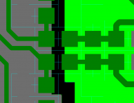
The grey and light green areas are copper pours, the pads are connected without any thermal relief. This is standard practice for some SMD designs as it gives the optimum connection to the copper pour. The blue outlines are the component outlines, the split is down the middle of the ferrite.
looking at the design again I would move the caps fastened to the noisy ground (grey) to the same positions as their opposite numbers so the signals pass through the cap pins, just a bit better that way.
looking at the design again I would move the caps fastened to the noisy ground (grey) to the same positions as their opposite numbers so the signals pass through the cap pins, just a bit better that way.
- Status
- This old topic is closed. If you want to reopen this topic, contact a moderator using the "Report Post" button.
- Home
- Source & Line
- Analog Line Level
- Balanced line receiver (INA134) - RFI caps - compromise between CMRR/RFI filtering