Would it be in some way possible to delay a signal?
Like if I go from LOW to HIGH it does it pretty much instantly but if I go from HIGH to LOW there is an added delay?
Could it be possible to do that in hardware?
This could be a solution, if it was possible to do so.
Something like a cap that has to be discharged before the signal goes from HIGH to LOW, but then there is the issue with charging of the cap when going HIGH, that should be done more or less instantly, otherwise then the LOW to HIGH transition would be delayed as well.
EDIT : Hmm, using flip-flops might be a solution and building some sort of latching circuit with some form of delay.
Last edited:
I measured the "switching glitch" duration to around 500uS with 5VDC through the attenuator.
So it is there for a really short time but long enough for it to be clearly noticable.
None of my ideas to get rid of the "pops" seem to be any good after I have thought about it some more.
I am open for suggestions.
So it is there for a really short time but long enough for it to be clearly noticable.
None of my ideas to get rid of the "pops" seem to be any good after I have thought about it some more.
I am open for suggestions.
Last edited:
I think I got a brilliant idea. 
The problem here is most likely that the relays do not get to go fully on before they are turned off, which means that the magnetic fields aren't fully formed before turn off, this would result in the release time is faster that it would be if the relay were to go fully ON before being turned OFF. That is my theory anyway, don't know if it 's valid or not? It is just a thought and it might only apply in case of very fast rotation of the POT.
But what if we put all the output bits through a D Flip-Flop, driven by a 100 Hz clock, made by dividing down the 640kHz clock from the ADC0804.
Then every 10mS, the outputs from the D Flip-Flop would change according to whatever the inputs are fed with from the ADC0804 and then the relays would only change every 10mS, giving enough time for the realys to go fully ON with a fully formed magnetic field, before they are turned OFF.
Starts with all relays ON(full attenuation), 10mS - Some stay ON, others go OFF, 20mS - Some stay ON, some go ON(fast), some go OFF(slower than ON, due to flyback diode), repeat every 10mS.
or 
EDIT : Now that I think about it, the idea might not be that great anyway, argh.
The problem here is most likely that the relays do not get to go fully on before they are turned off, which means that the magnetic fields aren't fully formed before turn off, this would result in the release time is faster that it would be if the relay were to go fully ON before being turned OFF. That is my theory anyway, don't know if it 's valid or not? It is just a thought and it might only apply in case of very fast rotation of the POT.
But what if we put all the output bits through a D Flip-Flop, driven by a 100 Hz clock, made by dividing down the 640kHz clock from the ADC0804.
Then every 10mS, the outputs from the D Flip-Flop would change according to whatever the inputs are fed with from the ADC0804 and then the relays would only change every 10mS, giving enough time for the realys to go fully ON with a fully formed magnetic field, before they are turned OFF.
Starts with all relays ON(full attenuation), 10mS - Some stay ON, others go OFF, 20mS - Some stay ON, some go ON(fast), some go OFF(slower than ON, due to flyback diode), repeat every 10mS.
or EDIT : Now that I think about it, the idea might not be that great anyway, argh.
Last edited:
Perhaps try a simple RC filter or better an integrator with break frequency of around 1Hz, to ramp the volume slowly, even when the dial is turned rapidly. Rapid volume changes become impossible but all changes are smooth.
It sounds like this has been an educational project and you've experienced first hand some of the limitations of this type of attenuator. It probably sounds quite clean once set anyway and as you've noted maintains perfect channel balance
It sounds like this has been an educational project and you've experienced first hand some of the limitations of this type of attenuator. It probably sounds quite clean once set anyway and as you've noted maintains perfect channel balance
I have a solution.
I am not going into details before I have actually built a new version, but I can already say that this solution is guaranteed to work.
It is all about having the correct timing and delays where needed.
Hint :
1 x ADC0804, 2 x HEX D Flip-Flops, 1 x 14-bit Binary Counter, 1 x Inverter, 12 x BC850C.
First working, pop free Relay Attenuator done exclusively in hardware, no software needed?
It will be so.
Last edited:
I am not going into details before I have actually built a new version, but I can already say that this solution is guaranteed to work.
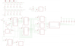
Not built it yet, but here is the schematic.
Attachments
If you use a current saving R + C feeding the relay coil, you get a faster ON than with the standard voltage.
eg 5V relay 100r coil uses ~ 50mA.
use 12V and a 150r resistor with a 22uF electrolytic and you will trigger the relay with 120mA for a couple of ms and then reduce the holding current to ~48mA. With the back emf diode you have faster ON and slower OFF.
eg 5V relay 100r coil uses ~ 50mA.
use 12V and a 150r resistor with a 22uF electrolytic and you will trigger the relay with 120mA for a couple of ms and then reduce the holding current to ~48mA. With the back emf diode you have faster ON and slower OFF.
If you use a current saving R + C feeding the relay coil, you get a faster ON than with the standard voltage.
eg 5V relay 100r coil uses ~ 50mA.
use 12V and a 150r resistor with a 22uF electrolytic and you will trigger the relay with 120mA for a couple of ms and then reduce the holding current to ~48mA. With the back emf diode you have faster ON and slower OFF.
Yes, that is an option as well.
But I decided against it and went the digital logic route instead.
Requires a handfull of components extra but it allows me to get very accurate timings and delays.
It is a pretty long explanation, but anyone that knows digital logic should be able to figure it out.
Last edited:
Yes, that is an option as well.
But I decided against it and went the digital logic route instead.
Requires a handfull of components extra but it allows me to get very accurate timings and delays.
It is a pretty long explanation, but anyone that knows digital logic should be able to figure it out.
A few more weeks and I should have something new to show.
I will make a new thread when the time comes.
Last edited:
Did some testing today.
I sent 5VDC through the attenuator and looked at the output with my oscilloscope and their indeed are short switching glitches which explains why I get a few "pops" when adjusting the volume.
The diodes included in the ULN2004 relay driver have a typical vF of 1.7V@350mA, more than regulaor diodes and this should give me a faster release time than if I had used regular diodes.
So I removed the ULN2004 common diode connection from +12V and let it float.
Instead I added external "normal" diodes with a vF of 0.850V@350mA. Again looking at the switching glitches on my scope this does seem to increase the release time of the relays since the switching glitches have been reduced in time.
Listening to the attenuator in my system with audio playing and adjusting the volume I still get "pops", which is as expected, however it does sound like what I saw on my scope carreid over to a real world usage scenario, the "pops" aren't as annoying as before. Great.
On their way to me is a bunch of Schottky diodes with a vF of 0.38V@350mA, which hopefully should increase the relay release times even more and result in a further reduction of the "pops" I get.
If that works out, bringing me almost close to home, I might implement what was suggested in post #3 and see if that could make me reach my goal of "pop" free operation.
One last thing, I got a solution to the relay chatter due to possible instability of the first LSB. It is nothing that has not been done before, I found the solution looking through old threads here on DiyA.
Sorry to necro an old thread, but I'm interested in your solution to the relay chatter from ADC LSB instability as I'm having exactly the same issue with an ADC0804-based relay attenuator. I couldn't find the old thread you referred to - please could you post your solution?
Sorry to necro an old thread, but I'm interested in your solution to the relay chatter from ADC LSB instability as I'm having exactly the same issue with an ADC0804-based relay attenuator. I couldn't find the old thread you referred to - please could you post your solution?
See attachment V2B, this is is how I do it currently, V3 is how it is going to work in V3.
V2B - look at U6,U8 and U10 and how they are connected. In V3 it is simplified and I now only use U6, which is now a single Non-Inverting/Inverting D flip-flop.
The end result is the same but much simpler.
You can also look in these 2 threads if you want some more inspiration :
V1 : Pop/click free HW-based relay attenuator
V2 : Pop/click free HW-based relay attenuator V2
V3 : Not completely done yet, but almost, the digital logic part of the circuit is the V3 attachment. The design is done except that I need to move 2 molex connectors a few mm.
Attachments
Last edited:
I also had an issue with chattering relays controlled by an ADC804. I took the following steps, which seems to have resolved the issue:
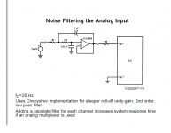
The noise went down to 90µV and the reference voltage drifts only a few mV from cold start. So far not a single chatter in about a week knocks on wood.
- opamp based noise filter as supposed in the datasheet on the analog input Vin as close to the adc804 as possible
- shielded cable for the analog pot
- added decoupling caps on Vcc (20uF+100nF), Vin+Vref/2 (0,5uF + 100nF) soldered directly on the chips pins
- replaced TL431 voltage reference for the analog input with a 0,4%, low temp coeff type
The noise went down to 90µV and the reference voltage drifts only a few mV from cold start. So far not a single chatter in about a week knocks on wood.
Attachments
- Home
- Source & Line
- Analog Line Level
- ADC0804 Relay Attenuator