Yes, but with a severely compromised frequency response at LF.
A little reading on transformers may help you get the best out of them. They don't provide power gain, just impedance matching and ground isolation. The voltage gain can be useful, but it isn't real gain - just a transformed impedance.
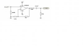
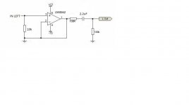
The current implementation I am using is simply employing the transformers to get the 0.01vrms of my dac up to a "workable" level. Attached is the gain stage I am currently using to feed my power amp (it's a reworked version of the second stage of Rod Elliott's P88) - with these transformers between the dac output (10R passive i/v) and the opamp circuit, the overall gain is roughly 30dB.
Although I can't notice much frequency loss on the LF side of things, is there any way of improving this implementation?
Attachments
Last edited:
Sorry, I got things back to front. Lower resistance than the transformer was designed for will reduce HF, not LF. However, you have a 10R source and 100k load with a transformer designed for 600:10k. I'm not sure how well that will work. You may need to measure it, with a test CD.
The original 100k load appears to be recommended by Rod Elliott when using a stepped attenuator prior to the opamp stage, but in this case there is no attenuator (I'm simply controlling the volume in the digital realm, via JRIVER) so the reducing the input impedance of the opamp stage shouldn't be too difficult, merely a matter of changing the 100K resistor to ensure it is > (166x10) = 1.6k?
I would be tempted to change the 100k for 10k and leave it at that. However, when I said "I'm not sure how well that will work" I meant that as a statement of my own ignorance rather than a statement of disapproval.
With transformers two things you need to watch out for are LF droops with too high resistances (inductance too low) and HF peaks and droops with too high resistances (insufficiently damped resonances). Measurement is the best option.
With transformers two things you need to watch out for are LF droops with too high resistances (inductance too low) and HF peaks and droops with too high resistances (insufficiently damped resonances). Measurement is the best option.
Last edited:
Hi,
Why use 10R resistors on the DAC ? Surely it can manage more voltage swing ?
E.g. 1K loads for a nominal 1V peaky to peak = nominal ~ 300mV line level ?
With balanced DAC with current outputs why not load each channel with 2 x 300R,
used balanced XLR as an interconnect, the tranny as XLR back to single ended ?
Should end up with a pretty healthy signal level to go to the volume pot,
with low enough source impedance to drive a typical volume pot.
rgds, sreten.
I've read a lot about the various resistances one can use on a passive iv and the consensus seems to be < 100R gives the lowest distortion. I tried the AD1865 in balanced format with these transformers which gave 55mV into Broskie's "unbalancer" tube circuit, and the sound is fantastic.
Perhaps you are correct, I could try increasing the iv resistors to 300R, then run it straight into the 600:10K transformers, bypassing the need for a tube (or opamp) gain stage.
I'll report back again - is this is the correct wiring for this arrangement?
XLR out (from DAC) to transformer
Red +
Black GND
Green -
Transformer Output
Yellow - RCA+
Blue - RCA GND
Audio Transformers - Bill Whitlock
Chapter 11 (3MB PDF)
From the "Handbook for Sound Engineers" Third Edition.
http://www.jensen-transformers.com/an/Audio Transformers Chapter.pdf
Chapter 11 (3MB PDF)
From the "Handbook for Sound Engineers" Third Edition.
http://www.jensen-transformers.com/an/Audio Transformers Chapter.pdf
I would be tempted to change the 100k for 10k and leave it at that. However, when I said "I'm not sure how well that will work" I meant that as a statement of my own ignorance rather than a statement of disapproval.
With transformers two things you need to watch out for are LF droops with too high resistances (inductance too low) and HF peaks and droops with too high resistances (insufficiently damped resonances). Measurement is the best option.
By way of update - I've dropped the input impedance of the opamp stage to 10k as recommended. I can't say for certain how this has affected the sound as I don't have the tools to measure the frequency response, however the sound is certainly pleasing enough.
I've also modified the opamp stage so that it is unity gain, as the transformer's gain is good enough to drive a high impedance power amp, but this buffer stage gives a nice low output impedance.
Can anyone advise whether the 100R resistors (prior to the 2.2uF output caps) are still required? I don't know what purpose they serve - presumably some kind of RF filtering?
Attachments
You are one step ahead of me - I want to use the 100R resistors as the IV resistors, as they are Takman good quality. So I figured if I replace the 100R with a wire link I can steal them.
If I keep the cable between the opamp buffer and the power amp to, say, less than 50cm, are the 100R necessary?
If I keep the cable between the opamp buffer and the power amp to, say, less than 50cm, are the 100R necessary?
It is always best to include some resistance in series with a follower output. This stops the follower directly seeing the capacitance of the load, which can cause instability. A shorter cable means less capacitance, which may simply mean higher frequency oscillation. The 'quality' of these resistors is almost immaterial as they don't do much at audio frequencies. Use whatever you have.
- Status
- This old topic is closed. If you want to reopen this topic, contact a moderator using the "Report Post" button.
- Home
- Source & Line
- Analog Line Level
- 600:10k line stage transformers any use?