Wanted: Simple 80Hz Linkwitz-Riley 24hz/octive ready to print, etch, and construct low pass filter PCB. After a few months of searching ‘The Google‘, I can‘t find any such thing, and even though I am electrically illiterate, I think that I am ready to try my hand at printing-out a PSB board and soldering it up if that is all I have to accomplish and if anyone knows of such a thing and will hold my hand while I attempt this new endeavor. ")
I own four sets of home stereos based on PA speakers (2 Altecs, 1 PV, and 1 EV) and all of them sound great, but are crying out for subs. It might just be cheaper to purchase four Crown XLS 1000 Drivecore amps with built in low pass filters, but I need and would at least like to try building one.
I own four sets of home stereos based on PA speakers (2 Altecs, 1 PV, and 1 EV) and all of them sound great, but are crying out for subs. It might just be cheaper to purchase four Crown XLS 1000 Drivecore amps with built in low pass filters, but I need and would at least like to try building one.
Last edited:
ESP also has information on this and you could buy his P09 PCB and just use it as a low-pass section:
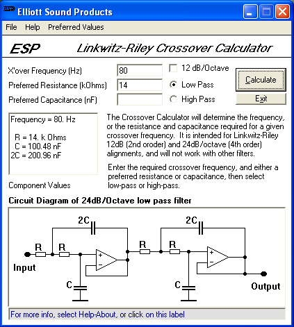
Linkwitz-Riley Electronic Crossover
Alternatively, you will almost certainly find the performance of a stripboard construction filter satisfactory.
You can build the filter for 80Hz break frequency using 14k resistors and 100nF capacitors:
Linkwitz-Riley Electronic Crossover
Alternatively, you will almost certainly find the performance of a stripboard construction filter satisfactory.
You can build the filter for 80Hz break frequency using 14k resistors and 100nF capacitors:
Attachments

Pick the cap first. They come in fewer values.
If you can measure the cap to better than tolerance, use the measured value.
Resistors can be adjusted by series and parallel additions.
The example has 14k and ~100nF, try 150nF and then your resistor ~10k. Even lower (5k to 7k) will have less noise.
If you can measure the cap to better than tolerance, use the measured value.
Resistors can be adjusted by series and parallel additions.
The example has 14k and ~100nF, try 150nF and then your resistor ~10k. Even lower (5k to 7k) will have less noise.
It actually is more practical to pick capacitor first, since there are fewer values available. Resistor values should be between about 1k-30k, too low and the op-amp gets loaded down, too high and noise increases (not too big a deal with 80Hz break LPF mind!).
Capacitor value doesn't strictly matter so much but you should select a resistor large enough to afford use of a commonly available film type capacitor, since electrolytic types do not have close enough tolerances to produce an accurate filter without matching.
The values of 14k and 100nF should work well and even a TL071/072/074 op-amp will have no problems with loading here
Silicon Chip magazine (Australia) has plans and layout for an active crossover. More elaborate than you need, but possibly a portion of the layout could be used as a pattern. Silicon Chip Online - Active 3-Way Crossover for Loud Speaker Systems
If you can get rub-down PCB resist patterns, it's not too hard to duplicate a layout. One trick I found was to drill the board first, and then just play connect the dots. That requires sharp (carbide) drill bits, because steel bits will wander too much unless you help them by making a divot with an icepick or something. So, if you don't have carbide bits, just mark the holes with the icepick and use those as the guide. Then drill after etching the board. This is also good if you're using a resist pen. The patterns and traces may be ugly, but at least the holes will be on the proper grid so it'll look tidy from above.
Or, just get some prototype PC boards from eBay; these ones are FR4 (not phenolic):
"3 PCS FR4 Prototype circuit bread Board Type 167x55mm" or the same seller has 6 phenolic for the same price.
You can get the PCB design from:
Crossover Linkwitz-Riley para sistemas 2.1
Crossover ó Divisor de 3 vias
One of them is my own design and the other one is from siliconchip AFAIK. They are way more than you need, but you can build only the low pass section.... That forum is for spanish speaking people, but google translator can help you...
You can just buy one, ready to go, at Marchand Electronics:
XM1 Electronic Crossover Network
Edit: this is the crossover board, assembled, but not including the power supply, although you could also buy that from them as well.
The products are good quality - I have used the XM1 before. Make sure you specify the desired Xover frequency when ordering.
XM1 Electronic Crossover Network
Edit: this is the crossover board, assembled, but not including the power supply, although you could also buy that from them as well.
The products are good quality - I have used the XM1 before. Make sure you specify the desired Xover frequency when ordering.
Thanks for the replys. A so called bread board would be fine to cut my teeth on. I was at mouser's site and noticed that there are hundreds of TLO71 chips. I also assume I need a power supply, a chip holder and what ever else. I really need someone to write up a parts list for me since I am such an idiot.
That Marchand XM1 looks nice at $40, but I think that I really want to build one from scratch all on my own.
PS. This will also be in stereo, so two of everything.
That Marchand XM1 looks nice at $40, but I think that I really want to build one from scratch all on my own.
PS. This will also be in stereo, so two of everything.
Last edited:
- Status
- This old topic is closed. If you want to reopen this topic, contact a moderator using the "Report Post" button.
- Home
- Source & Line
- Analog Line Level
- Wanted: 80Hz Linkwitz-Riley 24hz/octive low-pass filter