Hi Guys
Bear, I believe that the suggested rewiring of the bias gen collectors just converts the circuit to a true diamond of one form or another. Whether the collectors of the drivers go to the rails, to the output emitters or to the output node is almost immaterial. However, I suspect that having more voltage across the drivers is beneficial as it reduces devices capacitance.
With such a rewiring, one would also have to eliminate the divider between the output bases and feed the signal into the driver bases. Another current source would be required from the negative rail. The current sources would effectively control the output idle current, but all four devices would require emitter resistors for the currents to be controllable. As a true diamond, there is more current gain and potentially less THD.
As the circuit sits now (as linuxguru drew it), the current source value has no bearing on the idle current. Rather, the Vbe of the driver is working against the Vbe of the output plus the voltage drop across the output's emitter R. There is actually potential for the driver to run warmer than the output - current-wise.
Have fun
Kevin O'Connor
So instead of going to the + rail, the lower driving transistor would connect to junction of the output run off the + rail and its emitter resistor...
If it's a conventional diamond-buffer with that scheme, it's well known, but still needs two additional current sources for biasing (like all diamond buffers).
The scheme won't work with a 2-stage Douglas Self Type I or Type II EF (i.e. discrete darlington). With a CFP output, maybe cross-coupling could be made to work.
Ok, I can't find by search the thread where there was a diamond buffer with simulation results and then the OP did the circuit as was just suggested and posted the improvement (slight but noticeable).
This is a link to another version that uses the basic topology, right hand side of image, skip the last two output devices for the basic idea.
http://www.diyaudio.com/forums/solid-state/189123-anyone-built-power-diamond-buffer-amp.html#post2573832
This is a link to another version that uses the basic topology, right hand side of image, skip the last two output devices for the basic idea.
http://www.diyaudio.com/forums/solid-state/189123-anyone-built-power-diamond-buffer-amp.html#post2573832
Crud, wish I could find the simple and properly connected version.
No doubt it is sitting on my drive, mocking me.
This is a more compex version by jcarr, here on DiyAudio...
and another... used in an accuphase amp...
No doubt it is sitting on my drive, mocking me.
This is a more compex version by jcarr, here on DiyAudio...
and another... used in an accuphase amp...
Attachments
Hi Guys
The jcarr looks like an attempt to be "current on demand", something that is used in ICs to allow low idle currents. Not so much of a concern with discretes.
The other (thumbnail) is pretty conventional, looking like the front of the triple variation in Cordell's book - depends where R9,10 tie to.
In both cases, there is a standard diamond at the core, used in a conventional way. linuxguru's "diamond like" is not diamond-like at all. Just a comp EF with cross-coupled bias gen.
Have fun
Kevin O'Connor
Exactly, this is what is in front of one of Cordell's output stages, but first seen by me when published by Chris Paul in the 70s... the cross coupling buys some extra linearity.
Just wondering how the two approaches, the OP's and this one compare in practice. Regardless of linuxguru's EF with cross coupled bias gen as you term it, the only real question is performance and sonics (assuming one could hear the difference between these very low distortion buffer circuits... leave that question for another thread).
The other thought I had is that some of the buffers suggested in other threads are very interesting and seem to offer astoundingly great (very low ) distortion figures, but in practice need to be tweaked and twiddled in various fashions in order to even approach what the sim shows. So, another factor that is not oft considered is how robust the design might be, or tolerant of variations in various parameters (including the gain and linearity of the active devices). A more tolerant circuit would yield better results for the average builder. (that being one without all the test gear and drawers full of various devices to select from).
_-_-
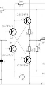
As the circuit sits now (as linuxguru drew it), the current source value has no bearing on the idle current. Rather, the Vbe of the driver is working against the Vbe of the output plus the voltage drop across the output's emitter R. There is actually potential for the driver to run warmer than the output - current-wise.
Actually, the CCS current sets the quiescent current in the output stage. The CCS current splits between the base current in the EFs (small), the voltage divider resistor network (small and almost constant) and the emitter current in the cross-coupled bias-setting BJTs (almost all of the CCS current).
About 2x (bias-BJT Vbe drop + the drop across the bias-BJT emitter resistor) is matched by 2x (EF-BJT Vbe drop + the drop across the EF-BJT emitter resistor). Hence, the output stage bias current can be adjusted by adjusting the ratios of those two resistors - almost like a current-mirror with gain. As shown, with a 10:1 ratio between those resistors, the split in currents is 1: <10 (a bit lower because the Vbe isn't the same in the bias stage and the EF).
With AC swing at the PNP base, there's push-pull current swing in the output stage, depending on the load Z. The additional base-to-base capacitance serves to make the amplitude of the current swing nearly equal in the NPN and PNP EFs, at high-enough frequencies (when the base-to-base capacitance is an AC short).
Without the cap, it still works, because the (impedance of the CCS + base and emitter loads) is large (>100s of kohms) compared to the Z of the voltage-divider network (a few kohms). However, amplitude of the push-pull current swings in the NPN and PNP will be mismatched a bit without the base-to-base cap, contributing to higher THD20 (though not necessarily bad for sonics, since it's H2 that dominates for typical EF bias currents and loads).
The main virtues, apart from Class-A sonics and current-boosting, are these:
1) It's simple enough to fit within an ~12 x 12 mm form factor along with a SOIC opamp;
2) It works with almost any standard SOIC single opamps;
3) Output stage quiescent current is stabilized, even with moderate mismatch between all actives - it depends mostly on the CCS current and the resistor ratios as mentioned above;
4) Output offset between the opamp output and the EF output is moderate, at ~1V - which gets servoed by the opamp in normal use at any rate.
Last edited:
Hi Guys
Most complimentary circuits are sensitive to gain difference of the circuit halves. The easy way to reduce this sensitivity and to not require tight if any matching is to incorporate emitter degeneration everywhere.
There are compromises with every choice.
Have fun
Kevin O'Connor
Most complimentary circuits are sensitive to gain difference of the circuit halves. The easy way to reduce this sensitivity and to not require tight if any matching is to incorporate emitter degeneration everywhere.
There are compromises with every choice.
Have fun
Kevin O'Connor
Last edited:
- Status
- This old topic is closed. If you want to reopen this topic, contact a moderator using the "Report Post" button.
- Home
- Source & Line
- Analog Line Level
- Diamond Cascode, a Diamond-like buffer/current booster