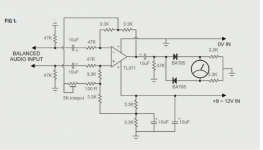
That looks like a line level input.
Balanced line levels can be as high as 10Vac from pole to pole (Hot to Cold).
The gain around the opamp cuts the line level signal to ~28% (-11dB).
Could someone explain which part of the circuit achieves the VU ballistic?
Or is the fast attach and slow decay done elsewhere?
Balanced line levels can be as high as 10Vac from pole to pole (Hot to Cold).
The gain around the opamp cuts the line level signal to ~28% (-11dB).
Could someone explain which part of the circuit achieves the VU ballistic?
Or is the fast attach and slow decay done elsewhere?
Thats a bridged amplifier so I think your circuit would work by just connecting it across the speaker.
Given a high enough signal you don't even need the opamp, the meter part of the circuit fed via that 10uf cap from either speaker terminal would work just as well... yes you would have to optimise it but as far as ballistics go etc it would be just the same. As long as there was enough signal it would be OK.
As far as the whole circuit goes, I think you just have to try it. I can't see it achieves anything in the way of a predetermined attack and decay and I suspect the meter will barely move on transients.
Thats a bridged amplifier so I think your circuit would work by just connecting it across the speaker./QUOTE]
P { margin-bottom: 0.08in; } [FONT=Times New Roman, serif]That's really interesting that the circuit might work with the op-amp accross the speakers. With my first attempt (s. Attach) the meter responded but only at very high volume. I'm not in search of any high-accuracy ballistics here, all I want is a dancing needle [/FONT][FONT=Times New Roman, serif]♫......(I know...weird) at normal listening volumes so maybe the op-amp will give it the needed amplification. Thankful as always, that was very useful, I'll try it tomorrow [/FONT]
Attachments
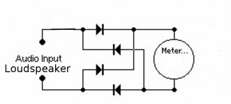
Sorry, I didn't make it clear... the full circuit would work connected across the speaker, or ac couple the meter and diodes across just one speaker lead and ground, perhaps with a series resistor. There is often another cap across the meter to slow its response down. Do a search for ''passive power meters'' and passive VU meters.
100W into 8ohms is equivalent to 40Vpk into the load.
Subtract the diode drops and the meter will see ~38.6Vpk.
Listen at an average level of -10dB relative to maximum (10W average) and the meter will see ~11.5Vpk
Listen at -20dB relative to maximum (1W average) and the meter will see ~2.6Vpk but of a quite short duty cycle, probably less than 30% bringing the effective average reading meter signal to ~ 0.9Vpk.
Design your meter circuit to not blow up at maximum output and at normal listening levels the meter will display a reading of ~2.3% of full scale deflection.
You will not get a dancing needle.
Read up on what VU meters do.
Read up on how VU meters achieve useful display.
Read up on how to build an effective VU meter.
That’s all very interesting, AndrewT. Unfortunately I don’t have the test equipment to read „pure“ peak-to peak audio levels, what I have is a VU meter that refuses to budge at normal listening levels.
Quote “Read up on what VU meters do.
Read up on how VU meters achieve useful display.
Read up on how to build an effective VU meter.”
I’ve already spent way too much time on what, after all, is a rather simple moving-coil meter. Now I just need a solution, this isn’t rocket science!
And thank you all for your patience
A meter bought as a VU meter with a -20 to +3 scale normally has inbuilt diodes and a resistor and could give a reading of zero with a line level of 0.775 volts RMS or 1.228V RMS and wouldnt need external diodes ,external resistance yes if you intend putting it across speaker terminals . The problem you have with making it respond at normal listening levels at the speaker terminals is you are likely to bend it when you inadvertently whack the volume up.
Getting a meter to respond well to typical signals without being damaged by peak signals is not "rocket science" but neither is it completely trivial. Understanding the problem can sometimes help in finding a good solution.stoppage said:I’ve already spent way too much time on what, after all, is a rather simple moving-coil meter. Now I just need a solution, this isn’t rocket science!
As others have said, your original circuit appears to have no 'ballistics' components. It is merely a buffer amp followed by an AC coupled rectifier.
There's nothing about ballistics (the speed of the indication in a changing volume level) in that circuit. All the ballistics there is determined by the mechanics of the meter movement.
What it appears you want is a "power meter." This is sometimes done with a diode (or maybe two in series to drop enough voltage) in parallel with the meter (in addition to the other rectification circuitry - I'd just use a single diode and resistor for half-wave rectification), so that it responds logarithmically instead of linearly. This will give you meter deflection at most volume levels, but it won't 'dance' as much (it won't move as far with variations in sound loudness). If I were to "design" the meter driving circuitry for a "real product" I'd use a microcontroller and be done with it...
What it appears you want is a "power meter." This is sometimes done with a diode (or maybe two in series to drop enough voltage) in parallel with the meter (in addition to the other rectification circuitry - I'd just use a single diode and resistor for half-wave rectification), so that it responds logarithmically instead of linearly. This will give you meter deflection at most volume levels, but it won't 'dance' as much (it won't move as far with variations in sound loudness). If I were to "design" the meter driving circuitry for a "real product" I'd use a microcontroller and be done with it...
Last edited:
Cheaper meters "bought as VU Meters" from Ebay quite often do not in fact include inbuilt diodes.A meter bought as a VU meter with a -20 to +3 scale normally has inbuilt diodes and a resistor and could give a reading of zero with a line level of 0.775 volts RMS or 1.228V RMS and wouldnt need external diodes
What I want is a VU MeterWhat it appears you want is a "power meter."
O.k., given that what I need is a proper ballistics circuit, two questions....with my current setup the meter works perfectly well connected across the speaker but only at very high volumes (using Bridge rectifier, Schottky diodes). Will a ballistics circuit operating from line-level rectify this? Does anybody know where I find a suitable circuit (basic as possable, preferably TDA071 no negative supply rail)?
Thank you
Thank you
O.k., given that what I need is a proper ballistics circuit, two questions....with my current setup the meter works perfectly well connected across the speaker but only at very high volumes (using Bridge rectifier, Schottky diodes). Will a ballistics circuit operating from line-level rectify this? Does anybody know where I find a suitable circuit (basic as possable, preferably TDA071 no negative supply rail)?
Thank you
Yes, but I haven't a circuit I can show you. You need to remove the forward volt drop of the diodes which is easy by incorporating them in the feedback loop of an opamp. Thats a pretty satndard technique to come up with a full wave rectifier with no diode volt drop.
Why don't you look up some old service manuals, the old Jap amps of the 80's like Hitachi and Technics that used massive meters on the fronts and look at the circuitry in those, which I should add I have no idea what they were like or used.
You say that, but I don't think that's what you want.What I want is a VU Meter
And that is 0dB or +3dB in reference to WHAT? One volt RMS? One milliwatt into 600 ohms? One watt into 8 ohms?OK,
how do we set up a VU meter to read correctly?
Is it set with a continuous sinewave @ a specific frequency?
Is it set to 0dB, or to +3dB?
What should that indicate? The onset of clipping, or the onset of distortion, or the onset of excessive distortion?
Ballistics refers ONLY to the TIME it takes for a meter to show an accurate indication after the volume is changed. It seems to me you're not concerned with this.O.k., given that what I need is a proper ballistics circuit,
I of course can't be sure, but I think you're looking for a circuit as I described earlier, that will show meter indication over a wide range of power levels. Look for schematics of the meter circuits in old high-power amps as Mooly suggests:
They're likely "power meters" (with a logarithmic display of watts into 8 ohms) though they might also say "VU" on them since any kind of metering of audio levels tends to get labeled VU whether it corresponds to actual VU meter specs or not.Yes, but I haven't a circuit I can show you. You need to remove the forward volt drop of the diodes which is easy by incorporating them in the feedback loop of an opamp. Thats a pretty satndard technique to come up with a full wave rectifier with no diode volt drop.
Why don't you look up some old service manuals, the old Jap amps of the 80's like Hitachi and Technics that used massive meters on the fronts and look at the circuitry in those, which I should add I have no idea what they were like or used.
- Status
- This old topic is closed. If you want to reopen this topic, contact a moderator using the "Report Post" button.
- Home
- Source & Line
- Analog Line Level
- VU Meter ballistics