Hi everyone,
I am planning on embarking on a new amplifier project starting with a preamp I built many years ago, but I am very much a dabbler when it comes to electronics.
I would like to use a remote control for the preamp and thought I would use an arduino to receive the remote signals and also drive a motorised pot for the preamp volume.
The question I have is, I would like to send feedback on the pot position to the arduino to allow some different decision making and possibly an LCD display relating to the volume level. Is it possible to provide this feedback information to the arduino but also keep a suitable level of isolation from the audio circuit so that noise isn't introduced.
Any thoughts / suggestions?
Thanks.
I love my motorized volume pot with remote control and would not want to live without it. The only feedback mine has is an LED on the volume knob, so I can see it move and see what the setting is.
What feedback does the motorized pot provide?
What kind of motor does it have? Is it a stepper motor?
Is there a separate rotary position encoder, or tachometer?
Where would the display be? On the remote?
One nice feature would be a settable stop, above which the knob would not normally go.
Is this a package you're thinking of purchasing, that includes the handheld and the receiver and the motorized pot?
Separating the power supply would probably be the main way to isolate it. And don't make any antennas with the wiring, i.e. keep all pairs tightly twisted.
DUG,
Thanks for the suggestion, but I am not 100% sure of what you are proposing and how I would achieve this.
gootee, The motorized pot is a fairly straightforward ALPS one. It doesn't provide any feedback as such but I thought I could use the POT in some sort of feedback loop.
The more I think about this the more I think the better thing is just to go for the old KISS principle and Keep It Simple.
I will get everything working first and then if I want to expand on the functionality that is the time to do it.
Thanks so much for the feedback guys.
DUG,
Thanks for the suggestion, but I am not 100% sure of what you are proposing and how I would achieve this.
...
Attachments
Maybe a low-value current-sense resistor could be added in series with the audio signal, downstream of the pot. Then use two instrumentation amplifiers, one to measure the voltage across the current-sense R and one to measure the voltage across the input and output of the pot. Then calculate the current (using the known value of the current-sense R) and divide the voltage across the pot by the current, to get the pot's resistance. You could also calculate the voltage-divider ratio of the pot and it's -dB gain factor.
You would want to sample the voltages at about the same time. And you might want to low-pass filter the outputs of the instrumentation amps, and/or average the final results over the last n samples (or low-pass the final result, if calculating it with analog only).
If you hand-matched resistors, you could make the instrumentation amps using two or three op amps each, instead of buying them.
If no digital processor was desired, an analog multiplier/divider chip could be used (or even a discrete version made with transistors).
Application Notes AN-20 and AN-31 from ti.com should have everything needed. And analog.com has good analog multiplier/divider chips.
Last edited:
Putting DC across the pot is not such a good idea. For a start you might well introduce severe crackling noise into the signal path.
If you have the space, I would put a gear onto the pot shaft and use the gear to drive another positional sensor, be-it a pot or an optical encoder. Then use the output of that sensor to determine the position of the audio pot.
If you have the space, I would put a gear onto the pot shaft and use the gear to drive another positional sensor, be-it a pot or an optical encoder. Then use the output of that sensor to determine the position of the audio pot.
Last edited:
sampling
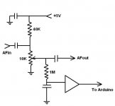
I'm currently using arduino to sample the input and output signal, then calculate the difference in dB rms and it works nice, just though there might be a more better solution, and yes I have space to mount some gear just needed the KISS principle and if it gets complicated i might drop this at all. or do the PGA2311, but I love the ALPS motorized pot.
Attaching the current circuit using arduino
Sampling is done in 50 ms for input and output then calculation of dbv
peakToPeak = signalMax - signalMin; // max - min = peak-peak amplitude
double volts = (peakToPeak * 3.3) / 1024; // convert to volts
double dbv = 20 * log10(volts*0.707);
but is bit unstable for a signal that is non LINE-LEVEL in the lower end of the pot
So I prefer hw solution to this problem.
I'm currently using arduino to sample the input and output signal, then calculate the difference in dB rms and it works nice, just though there might be a more better solution, and yes I have space to mount some gear just needed the KISS principle and if it gets complicated i might drop this at all. or do the PGA2311, but I love the ALPS motorized pot.
Attaching the current circuit using arduino
An externally hosted image should be here but it was not working when we last tested it.
Sampling is done in 50 ms for input and output then calculation of dbv
peakToPeak = signalMax - signalMin; // max - min = peak-peak amplitude
double volts = (peakToPeak * 3.3) / 1024; // convert to volts
double dbv = 20 * log10(volts*0.707);
but is bit unstable for a signal that is non LINE-LEVEL in the lower end of the pot
So I prefer hw solution to this problem.
Last edited:
Why make it so difficult? As far as I understand we talk about an amp to-be-designed, so the pot may be freely chosen. Many motorized pots (e.g. ALPS RK168) are available with 4 layers, so you could take layer 1+2 for audio, gound layer 3 completely and feed clean low voltage DC into layer 4 to send the wiper directly into arduinos ADC.
At least this is what I would do")
BR,
Holgi
At least this is what I would do
BR,
Holgi
nice
Yesterday I was just thinking the same. And maybe this is by now the most simple solution. If there is no other solution I might sell the 2 channel and get one 4 channel pot, if there is no other solution.
Why make it so difficult? As far as I understand we talk about an amp to-be-designed, so the pot may be freely chosen. Many motorized pots (e.g. ALPS RK168) are available with 4 layers, so you could take layer 1+2 for audio, gound layer 3 completely and feed clean low voltage DC into layer 4 to send the wiper directly into arduinos ADC.
At least this is what I would do
BR,
Holgi
Yesterday I was just thinking the same. And maybe this is by now the most simple solution. If there is no other solution I might sell the 2 channel and get one 4 channel pot, if there is no other solution.
nice
Yesterday I was just thinking the same. And maybe this is by now the most simple solution. If there is no other solution I might sell the 2 channel and get one 4 channel pot, if there is no other solution.
Also found this part that might be used as add-on layer
http://uk.farnell.com/bourns/3382g-1-103g/position-sensor-resistive-3pin/dp/1717387
this should simply fit in nicely so no need for new pot. if i go with this solution.
Why make it so difficult? As far as I understand we talk about an amp to-be-designed, so the pot may be freely chosen. Many motorized pots (e.g. ALPS RK168) are available with 4 layers, so you could take layer 1+2 for audio, gound layer 3 completely and feed clean low voltage DC into layer 4 to send the wiper directly into arduinos ADC.
At least this is what I would do
BR,
Holgi
Yesterday I was just thinking the same. And maybe this is by now the most simple solution. If there is no other solution I might sell the 2 channel and get one 4 channel pot, if there is no other solution.
Also found this part that might be used as add-on layer
http://uk.farnell.com/bourns/3382g-1-103g/position-sensor-resistive-3pin/dp/1717387
this should simply fit in nicely so no need for new pot. if i go with this solution.
Last edited:
I am working on the same thing: my plan is as Holgi suggests: use a 4 gang pot, with one gang dedicated to a sense input on the Arduino. I will put 5V across that gang, and measure the voltage at the wiper. That way I can completely isolate the sensing of position from the signal path.
More info here: http://www.diyaudio.com/forums/analog-line-level/241273-remote-control-preamp-works.html
More info here: http://www.diyaudio.com/forums/analog-line-level/241273-remote-control-preamp-works.html
Last edited:
Two thoughts on that one Tim.
1. You could use two of the gangs for position, one in reverse to error check the first.
2. There might still be a bit of noise from the DC across the sensing track so you could 0V the one between it and the sensitive audio tracks.
Good points. I will mock it up to make sure I have a control system that is reliable. I will also be able to check for noise on the audio gangs without audio. I am expecting that noise from the digital side of the project will be the biggest potential downside of a computer-controlled preamp.
My finding of this part 3382G-1-103G - BOURNS - POSITION SENSOR, RESISTIVE, 3PIN | Farnell United Kingdom
Rotary position sensor from Bourns, might not be the solution because of the shaft rotor diameter is small - only 4mm but the ALPS rotor is 5 or 6 mm
Also I could not find any motorized 4 channel ALPS that are 100K log.
Seems external through hole rotary sensor applied over the alps is the best isolation from signal and less expensive , if only I can find one with bigger hole diameter.
- Status
- This old topic is closed. If you want to reopen this topic, contact a moderator using the "Report Post" button.
- Home
- Source & Line
- Analog Line Level
- Motorised Volume Pot - Controller isolation