I'm trying to brainstorm a good way to measure the DC voltage component in a signal that has significantly more AC signal (volts) than DC (10's-100's of microvolts). I would like to bring the measurements into an Arduino so that I can monitor and further process the signal. The Arduino can measure voltages in the range of 0-5V but only with a resolution of 4.7mV (10-bit).
My rough plan is to remove all the AC signal above 1 Hz (filtering) and then increase the voltage of the remaining DC signal (gain) so that it better matches the Arduino's input voltage range. This will improve the measurement resolution. The 1 Hz corner will give me sufficient temporal resolution for my measurements.
I thought of using the following:
single pole passive-RC LP filter --> chopper stabilized op-amp buffer --> LTC1062 switched capacitor filter --> RC single pole LP filter with 40dB of gain using another chopper stabilized op-amp
Motivation for this signal processing chain:
I don't have any real world experience working with chopper stabilized op amps or the LTC1062, but it seems like it should work on paper.
Any other ideas are welcome.
-Charlie
My rough plan is to remove all the AC signal above 1 Hz (filtering) and then increase the voltage of the remaining DC signal (gain) so that it better matches the Arduino's input voltage range. This will improve the measurement resolution. The 1 Hz corner will give me sufficient temporal resolution for my measurements.
I thought of using the following:
single pole passive-RC LP filter --> chopper stabilized op-amp buffer --> LTC1062 switched capacitor filter --> RC single pole LP filter with 40dB of gain using another chopper stabilized op-amp
Motivation for this signal processing chain:
- The passive-RC LP filters will provide some attenuation and introduces no DC errors.
- The chopper stabilized op amp has very low DC offset and can buffer and feed the main filter
- The LTC1062 is a DC accurate 5th order LP filter. This provides the main filtering
- The RC filter on the second chopper stabilized op amp will filter out the clock frequency feed through from the LTC1062 and provide DC gain to the filtered signal so that I can improve the measurement resolution I will get using the Arduino.
I don't have any real world experience working with chopper stabilized op amps or the LTC1062, but it seems like it should work on paper.
Any other ideas are welcome.
-Charlie
IMHO
Delete the LTC1062 switched capacitor filter.
Your are adding AC components that you have to filter out later.
What does the model results show?
If I delete the LT1062 I don't have enough filtering. What's a "better" alternative???
The only AC components that the LTC1062 will add are 1/f noise and the clock feedthrough, which is 1mV(pk) and 100 times higher than the corner frequency, so it's easily removed with a simple RC post filter.
If not the LTC1062, what do you suggest for something for a 5th or 6th order LP filter?
-Charlie
Here is another approach that might work:
Use 2 or 3 amplifier stages to implement the LP filter and gain stages simultaneously. Even if I use FET input op amps, there will be some DC "error" introduced. But this DC error component will be very slowly varying on the time scale of minutes or more (I assume). So once a minute I could just replace the actual in-circuit measurement points with a grounded resistor of the same value and measure the DC offset. This should be only the DC error itself. Then I could just subtract the DC error from subsequent measurements inside the Arduino.
If the DC error changes very slowly and can be quickly measured, this would probably be a better approach. Not sure about these however.
-Charlie
Thinking a little more about this... I like the idea more and more. It would be best to just measure the DC error and subtract it from subsequent measurements. But it would be best if the error did not change much over time, e.g. with changes in temperature. So what is the op amp type that has the least bias current drift? Should I use a chopper stabilized type here, or is that not necessary and I should use some other type??
Last edited:
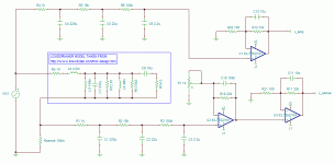
Hi, i was working on this for you before DUG posted, but i thought i'd post it anyway.
This works fine in Sim. You can choose a filter below 1Hz as i have, so a 12dB per octave one should be OK.
Use Ultra Low Offset OpAmps such as OPA177 for eg. You could use a 5k Ohm Trimpot for R6 to alter the gain to suit. And also make use of the OpAmps offset terminals to trim out any internal offsets.
Attachments
Hi, i was working on this for you before DUG posted, but i thought i'd post it anyway.
This works fine in Sim. You can choose a filter below 1Hz as i have, so a 12dB per octave one should be OK.
Use Ultra Low Offset OpAmps such as OPA177 for eg. You could use a 5k Ohm Trimpot for R6 to alter the gain to suit. And also make use of the OpAmps offset terminals to trim out any internal offsets.
Yes, thanks for the model and your thoughts.
It looks like you used a two single pole (first order) filters - I need at least 5 pole or more to get enough attenuation by 10Hz. Also, I don't want to reduce the corner frequency below 1Hz because the filter time constant becomes too long and I won't be able to measure second-by-second changes in the signal.
There is no way I want to trim out all those op amps!!! I'm thinking of using the LTC1052 (quad chopper op-amp) even though it is rather pricey.
So maybe three or four MFB LP filter stages with gain would work for my needs. I will sim that up tomorrow but would love to hear more feedback.
-Charlie
I was going to suggest a one-op-amp differential integrator op amp circuit, like is used for DC servos for amplifiers, with a one-op-amp DC-accurate 3rd-order active filter following the integrator.
Another thought occurred to me: Maybe you could use two of those RMS-to-DC converter chips, with one fed the original waveform and one fed a high-passed version of the waveform. Then subtract the output of the second converter from that of the first.
Another thought occurred to me: Maybe you could use two of those RMS-to-DC converter chips, with one fed the original waveform and one fed a high-passed version of the waveform. Then subtract the output of the second converter from that of the first.
I was going to suggest a one-op-amp differential integrator op amp circuit, like is used for DC servos for amplifiers, with a one-op-amp DC-accurate 3rd-order active filter following the integrator.
Another thought occurred to me: Maybe you could use two of those RMS-to-DC converter chips, with one fed the original waveform and one fed a high-passed version of the waveform. Then subtract the output of the second converter from that of the first.
Can you give me a part number for the RMS-to-DC converter ICs? I'm not familiar with them. I'd like to check out the specifications.
The only issue with the integrator is that you have to constantly reset it, since a DC signal will always be present.
If you can live with some ripple, you might be able to cascade a standard 2 to 4 pole filter with a Cauer or eliptic filter and get a very sharp skirt, using the standard filter to further drag the components above the steep drop down some more than the eliptic will do by itself.
What is the application that needs the measurement?
_-_-
What is the application that needs the measurement?
_-_-
Well I've been modeling all day and it seems that the bottom line is that the more amplifiers you throw at the problem the worse things look. So I changed the filtering to three single pole RC low pass filters, one after the other, with a 10x impedance difference between each one to minimize interaction. Then I used a couple of gain stages. I ended up doing the modeling with good ol reliable TL072s. Anyway, this is more or less working. I can track the voltage drop fairly well. I will need to sample the DC offset with the input grounded to zero that out of the equation, and hopefully the offset will be stable WRT time and temperature...
-Charlie
-Charlie
@ CharlieLaub
Well how about that ! I was next going to suggest removing the Active LPF & input OpAmp, & instead passively stringing @ least 3 x 6dB Oct 1Hz LPF's in series, @ the input to 2 x gain stages as in my screenie. The reason was due to your not wanting to do any offset trimming, so cutting out 1 stage would help.
If it works ok with TL072's, then") If not the OPA177's or similar Will do the trick
If not the OPA177's or similar Will do the trick
Keep us posted.
Well how about that ! I was next going to suggest removing the Active LPF & input OpAmp, & instead passively stringing @ least 3 x 6dB Oct 1Hz LPF's in series, @ the input to 2 x gain stages as in my screenie. The reason was due to your not wanting to do any offset trimming, so cutting out 1 stage would help.
If it works ok with TL072's, then
If not the OPA177's or similar Will do the trick Keep us posted.
After trying lots of different amplifiers, it looks like I do need to use a "zero-drift" or chopper stabilized type. The low tempco of a drift-stabilized amp means I only need to calibrate once and the input offset is very low as well.@ CharlieLaub
Well how about that ! I was next going to suggest removing the Active LPF & input OpAmp, & instead passively stringing @ least 3 x 6dB Oct 1Hz LPF's in series, @ the input to 2 x gain stages as in my screenie. The reason was due to your not wanting to do any offset trimming, so cutting out 1 stage would help.
If it works ok with TL072's, then
Keep us posted.
So far, a good choice seems to be the ICL7652 from TI. I will post some more info on the circuit, and the results of sims, shortly.
-Charlie
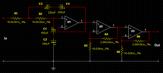
Here are more details on the circuit, and application.
GOAL:
The goal is to dynamically measure the voice coil resistance of a driver during use. A "sense" resistor is connected after the driver, to ground, and the driving amplifier has an intentional DC voltage offset of a few millivolts. The ratio of the voltage drop at DC across the driver and across the sense resistor can be used to determine the voice coil DC resistance, Re. The changes in Re with power input due to VC heating can be tracked by the circuit described below, with a time resolution of about 1 second. This should make it suitable for use with woofers and larger midrange drivers.
CIRCUIT DESCRIPTION:
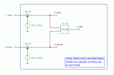
The circuit that I have been using to simulate this is attached below as "Driver_VC_resistance_measurement_circuit" and "Arduino_processing_of_VC_measurement". To sense the DC voltage I use three single pole RC low-pass filters, each having a corner frequency of about 1 Hz. The filtered signal is then sent through one or more gain stages. One gain stage operating on the voltage coming from Rsense is used to multiply by the ratio of Re/Rsense, which is 35 times using the loudspeaker model shown in the circuit. There are two separate measurements taken, one at the amplifier output and the other at the sense resistor. As shown in the attachment "Arduino_processing_of_VC_measurement" the gain-scaled voltages will be acquired by an Arduino, DC offset removed from each voltage feed, and then the ratio calculated. Because of the 35x gain stage mentioned above, the ratio of the voltages is now equal to Re(T)/Re(T=To) where T is the current temperature of the voice coil and To is some reference temperature (e.g. room temperature) to which the system was calibrated. Although temperature is not directly (or indirectly) measured it could be calculated using the tempco of the voice coil material. The Arduino is useful as way to monitor and display information and also because it is a simple matter perform the division operation in software. The Arduino can sample 0-5V with a 10-bit (4.7mv) resolution. In order to make better use of the range and resolution, the gain stages are used to bring up the nominal voltage to around 3V when a 10mV DC offset is supplied by the amplifier. The full 5V range could be used by increasing the amplifier's DC signal to 15mV, or by using more gain.
CIRCUIT SIMULATIONS (see attached figures):
THOUGHTS:
It looks like this circuit could work for dynamically measuring Re. In the sim, I have used a low-offset, chopper-stabilized op-amp that also has a very low DC-offset temperature dependence. This may make it possible to do a one-time calibration only. I need to check the influence of the tempco of the resistors in the gain stages, since these can also effect the performance. This may only be of concern if all the circuitry was located in the same housing as the amplifier or other heat-producing circuitry. If temperature dependence is not of concern, it may be possible to use other amplifiers depending on the amount of DC offset that will be produced. I have not make any effort to reduce DC offsets in the gain stages, and some changes in component values or topology (inverting gain stages?) might reduce the offset further. Any suggestions are welcome in this area.
One issue that I have not yet tackled is how to get the power amplifier to generate a reasonably stable DC offset of around 10mV. I thought that a DC servo could be used, but instead of trying to zero out the DC offset the servo would bring the offset voltage to the desired setpoint. Since I can directly measure the DC offset, I could also use one of the Arduino's output pins to send a voltage through a resistor to the amplifier's inverting or non-inverting input to control the DC offset. Both of these will require a dedicated amplifier design, e.g. you probably won't be able to use a commercial amplifier since few are DC coupled, unless by itself it happens to have an appropriate and stable DC offset...
That's where things stand for now...
-Charlie
GOAL:
The goal is to dynamically measure the voice coil resistance of a driver during use. A "sense" resistor is connected after the driver, to ground, and the driving amplifier has an intentional DC voltage offset of a few millivolts. The ratio of the voltage drop at DC across the driver and across the sense resistor can be used to determine the voice coil DC resistance, Re. The changes in Re with power input due to VC heating can be tracked by the circuit described below, with a time resolution of about 1 second. This should make it suitable for use with woofers and larger midrange drivers.
CIRCUIT DESCRIPTION:
The circuit that I have been using to simulate this is attached below as "Driver_VC_resistance_measurement_circuit" and "Arduino_processing_of_VC_measurement". To sense the DC voltage I use three single pole RC low-pass filters, each having a corner frequency of about 1 Hz. The filtered signal is then sent through one or more gain stages. One gain stage operating on the voltage coming from Rsense is used to multiply by the ratio of Re/Rsense, which is 35 times using the loudspeaker model shown in the circuit. There are two separate measurements taken, one at the amplifier output and the other at the sense resistor. As shown in the attachment "Arduino_processing_of_VC_measurement" the gain-scaled voltages will be acquired by an Arduino, DC offset removed from each voltage feed, and then the ratio calculated. Because of the 35x gain stage mentioned above, the ratio of the voltages is now equal to Re(T)/Re(T=To) where T is the current temperature of the voice coil and To is some reference temperature (e.g. room temperature) to which the system was calibrated. Although temperature is not directly (or indirectly) measured it could be calculated using the tempco of the voice coil material. The Arduino is useful as way to monitor and display information and also because it is a simple matter perform the division operation in software. The Arduino can sample 0-5V with a 10-bit (4.7mv) resolution. In order to make better use of the range and resolution, the gain stages are used to bring up the nominal voltage to around 3V when a 10mV DC offset is supplied by the amplifier. The full 5V range could be used by increasing the amplifier's DC signal to 15mV, or by using more gain.
CIRCUIT SIMULATIONS (see attached figures):
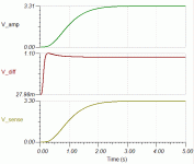
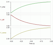
- "offset_calibration" shows the response of the circuit with the amplifier output grounded (no DC offset voltage). For this sim, the offset correction voltages in the Arduino were set to zero. The voltages stabilize to the DC offset of the circuit, and these are subsequently programmed into the Arduino to remove the effect of the small offset on the voltage ratio calculation.
- "Response_with_10mV_DC_input" is a sim of the circuit response with the DC offset corrections applied, and the amplifier set to have a 10mV DC offset (no AC signal present). The calculated ratio "V_diff" is very close to 1.0, meaning that the current value of Re is the same as when Re is at its "cold" value of 3.5 ohms (see loudspeaker model).
- "Response_with_10mV_DC_input_zoom" is the portion of "Response_with_10mV_DC_input" lying between 4 and 5 seconds, to more clearly show that V_diff is very close to 1.0.
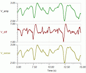
- "Response_to_music_input" is a sim of the circuit to a music input. This was done by reproducing the first 15 seconds of Tracy Chapmans' "Fast Car" by the amplifier with voltage swing up to about 40Vpk-pk. The response of V_diff still shows the correct value of 1.0.
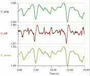
- "Response_to_music_input_with_Re_doubled" shows the effect of doubling Re in the loudspeaker model using the same "Fast Car" sim as above. V_diff has increased to approximately 2, indicating that Re has doubled.
THOUGHTS:
It looks like this circuit could work for dynamically measuring Re. In the sim, I have used a low-offset, chopper-stabilized op-amp that also has a very low DC-offset temperature dependence. This may make it possible to do a one-time calibration only. I need to check the influence of the tempco of the resistors in the gain stages, since these can also effect the performance. This may only be of concern if all the circuitry was located in the same housing as the amplifier or other heat-producing circuitry. If temperature dependence is not of concern, it may be possible to use other amplifiers depending on the amount of DC offset that will be produced. I have not make any effort to reduce DC offsets in the gain stages, and some changes in component values or topology (inverting gain stages?) might reduce the offset further. Any suggestions are welcome in this area.
One issue that I have not yet tackled is how to get the power amplifier to generate a reasonably stable DC offset of around 10mV. I thought that a DC servo could be used, but instead of trying to zero out the DC offset the servo would bring the offset voltage to the desired setpoint. Since I can directly measure the DC offset, I could also use one of the Arduino's output pins to send a voltage through a resistor to the amplifier's inverting or non-inverting input to control the DC offset. Both of these will require a dedicated amplifier design, e.g. you probably won't be able to use a commercial amplifier since few are DC coupled, unless by itself it happens to have an appropriate and stable DC offset...
That's where things stand for now...
-Charlie
Attachments
-
 Driver_VC_resistance_measurement_circuit.GIF18.8 KB · Views: 91
 -
 Arduino_processing_of_VC_measurement.GIF7.8 KB · Views: 86
 -
 offset_calibration.GIF6.9 KB · Views: 79
 -
 Response_with_10mV_DC_input.GIF9.3 KB · Views: 85
 -
 Response_with_10mV_DC_input_zoom.GIF8.5 KB · Views: 59
 -
 Response_to_music_input.GIF13.4 KB · Views: 26
 -
 Response_to_music_input_with_Re_doubled.GIF13.5 KB · Views: 28
Perhaps a silly question, but the changes in Re due to heating could be measured directly by merely heating the VC directly?
Or is there some factor in the heating when driven with "music" that may yield some other information?
The other thing is, capacitively couple an amplifier - maybe even with the F3 point being fairly higher than usual, >20Hz or more, and then inject a stable DC offset?
With nothing below >20Hz it might be easier to measure the DC?
_-_-
Perhaps a silly question, but the changes in Re due to heating could be measured directly by merely heating the VC directly?
Or is there some factor in the heating when driven with "music" that may yield some other information?
The other thing is, capacitively couple an amplifier - maybe even with the F3 point being fairly higher than usual, >20Hz or more, and then inject a stable DC offset?
With nothing below >20Hz it might be easier to measure the DC?
_-_-
No questions are silly...
To be more specific, the goal is to measure how a music signal is modulating Re, so directly heating the VC won't really be helping in this regard.
Yes, you MUST AC couple the amplifier or any signals below the corner frequency of the filters will pass, and then go through the gain stage. This would cause the op amps to saturate (bad). We only want to see the "DC" passing through Re and the sense resistor.
-Charlie
AC couple the *output* of the amplifier, then inject DC after the cap.
_-_-
That's already been done. See:
Hot Stuff: Loudspeaker Voice-Coil Temperatures | Stereophile.com
I think that my approach is simpler, since it uses the power amplifier itself to generate the DC signal.
-Charlie
Charlie,
I am curious what you are hoping to reveal through this experiment?
Seems to me that the conversion efficiency of loudspeakers is well known, as well as the "power compression" effects at high outputs (also high VC heating). Wondering what else you are looking for?
I am curious what you are hoping to reveal through this experiment?
Seems to me that the conversion efficiency of loudspeakers is well known, as well as the "power compression" effects at high outputs (also high VC heating). Wondering what else you are looking for?
Charlie,
I am curious what you are hoping to reveal through this experiment?
Seems to me that the conversion efficiency of loudspeakers is well known, as well as the "power compression" effects at high outputs (also high VC heating). Wondering what else you are looking for?
Once you can quantify something, then you are free to manipulate it in a prescribed way or compensate for it, and that can be advantageous in some applications. That non-answer will have to suffice for now.
- Status
- This old topic is closed. If you want to reopen this topic, contact a moderator using the "Report Post" button.
- Home
- Source & Line
- Analog Line Level
- designing a 1-Hz lowpass with no DC error