I made a 3 band equalizer following a Spanish Site
Construya un preamplificador con entrada de micrófono, línea y ecualizador
and here is the circuit in PDF
http://construyasuvideorockola.com/downloads/pretonos.pdf
It is a stereo preamp with 3 band equalizer module.
It was working okay for some 3 hours but suddenly it developed problem.
The sound is getting distorted after some 5 mins.
When I increase the bass control to the fullest extent, the sound stops altogether.
And sometimes the sound is distorted.
Disconnecting and reconnecting the power supply is fixing it for another 5 minutes.
They suggested to reverse the 1uf caps between TLO71 and TLO72 if distortion occurs or the sound stops. I tried that too.
But that didn't fix the problem.
I can't ask for help there as I don't know Spanish.
I am frustrated because I already wasted two precious pieces of PCB on it. and rebuilt again thinking I might have made some mistakes. But all my 3 attempts produced the same distorted result. 
My PSU is +- 15 volt dual regulated and working great with other circuits.
Is it a design fault of the equalizer module posted in that site?
So you all are my last resort as always.
Could you kindly check the circuit and help me out fixing this problem?
Any help is sincerely much appreciated.
Thank you.
Construya un preamplificador con entrada de micrófono, línea y ecualizador
and here is the circuit in PDF
http://construyasuvideorockola.com/downloads/pretonos.pdf
It is a stereo preamp with 3 band equalizer module.
It was working okay for some 3 hours but suddenly it developed problem.
The sound is getting distorted after some 5 mins.
When I increase the bass control to the fullest extent, the sound stops altogether.
And sometimes the sound is distorted.
Disconnecting and reconnecting the power supply is fixing it for another 5 minutes.
They suggested to reverse the 1uf caps between TLO71 and TLO72 if distortion occurs or the sound stops. I tried that too.
But that didn't fix the problem.
I can't ask for help there as I don't know Spanish.
I am frustrated because I already wasted two precious pieces of PCB on it.
and rebuilt again thinking I might have made some mistakes. But all my 3 attempts produced the same distorted result. My PSU is +- 15 volt dual regulated and working great with other circuits.
Is it a design fault of the equalizer module posted in that site?
So you all are my last resort as always.
Could you kindly check the circuit and help me out fixing this problem?
Any help is sincerely much appreciated.
Thank you.
Thank you so much Mooly!The circuit in the pdf won't work. Whats missing is a DC bias path to two of the opamps. Add a 470 K resistor from the "floating" + inputs on the opamps to ground.
Something like this?
Attachments
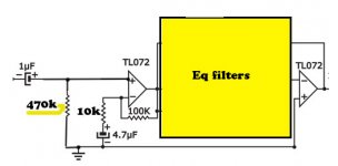
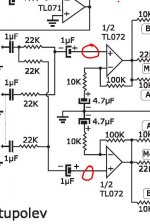
That's it
Its these two locations here.
You are such a kind and great resource person!
I will add the resistors and report you back.
Thanks a ton!
That's it
Its these two locations here.
I have no 470K at the moment. So I added a 560k. It's running fine so far.
Earlier problem has not come back yet.
Only the bass control response is so so.
I added this module in front of Project 88 Preamp by Rod Elliot.
The arrangement is like the following:
this 3 band Eq module > Rod's preamp > LM3886
1. Could you please tell me if project 88 preamp is still needed with this module or I can directly add this to my Power Amp using LM3886 omitting Rod's preamp?
2. Is there any better free DIY project like this 3 band EQ module with microphone input ( with PCB layout etc. ) that I can build?
( I tried APEX ML3 but microphone is not working as expected )
Thank you again so so much Mooly for your being here for us whenever we need.
Alternatively if you had used really poor quality 1uF caps they would have leaked enough current that the Opamp would just have just about had enough current to work, which is probably why they thought it was OK.
Regards,
Andrew
I thank you for your valuable input, Andrew.
I used fresh new good quality caps.
It's sad that they posted such a circuit without testing it much hence leading to utter frustration. But thank god I got experts like you all as constant help.
Much appreciated!.
Hi, this circuit should be Ok to drive power amp directly so you can remove preamp.
Is the microphone input working ok on this design as it has no phantom power supply. If you have a fairly good microphone it is likely it expects a phantom supply, even most PC microphones expect a bias voltage to work.
Regards,
Andrew
Is the microphone input working ok on this design as it has no phantom power supply. If you have a fairly good microphone it is likely it expects a phantom supply, even most PC microphones expect a bias voltage to work.
Regards,
Andrew
Pleased to hear its working
I wouldn't have thought you needed a pre amp as well as this because this tone control has gain. The microphone input is high gain (100) but has a really low input impedance (1K) so will not suit all mics.
I removed the Rod's preamp and connected this directly to LM3886.
Now this module is working nicely.
So a big thank you again
At present I'm using a 600 Ohm Mic, the response is very satisfactory as I have checked.
But in future I might purchase a professional mic.
So could you kindly suggest some modification to make the microphone work with all types of dynamic microphones?
Or is there any better professional easy to build circuit that is endorsed by you that I can build?
Hi, this circuit should be Ok to drive power amp directly so you can remove preamp.
Is the microphone input working ok on this design as it has no phantom power supply. If you have a fairly good microphone it is likely it expects a phantom supply, even most PC microphones expect a bias voltage to work.
Regards,
Andrew
Thank you Andrew, I've connected the preamp directly to the Power amp now. Working good.
The 600 Ohm mic I bought some days ago came with a 2 pin jack.
http://www.diyaudio.com/forums/atta...677432-mic-line-eq-preamps-mic-2-pin-jack.jpg
The performance of this mic when connected to this module is not too bad.
But I want to build a professional circuit to record voice with computer.
If you could kindly suggest some circuits with PCB layout that is easy to make it would be great.
Thank you.
You are best looking at building a separate mic preamp that suits the actual mic you end up buying. You need to look at the impedance the mic is designed to work into and also how much gain you need. A simple opamp circuit isn't always ideal in terms of noise etc when matching to a mic. A simple discrete circuit could be better.
You are best looking at building a separate mic preamp that suits the actual mic you end up buying. You need to look at the impedance the mic is designed to work into and also how much gain you need. A simple opamp circuit isn't always ideal in terms of noise etc when matching to a mic. A simple discrete circuit could be better.
Oh, thank you Mooly.
Could you please recommend such a discrete circuit for me to build?
It's not something I have ever built or looked into so you would have to search but some quick examples,
Low Noise Microphone Preamp
Low Noise Balanced Microphone Preamp
Low Noise Microphone Preamp
Low Noise Balanced Microphone Preamp
It's not something I have ever built or looked into so you would have to search but some quick examples,
Low Noise Microphone Preamp
Low Noise Balanced Microphone Preamp
Thank you so much Mooly
I will try those and ask for help if needed.
Mooly, could you kindly tell me if this circuit biasing is okay or not?
http://construyasuvideorockola.com/d_preamp_tonos.php
Here is the PDF
http://construyasuvideorockola.com/downloads/preamp_tonos_st.pdf
Should there be any difference sound wise between this one and the earlier one that you helped me fix?
http://construyasuvideorockola.com/d_preamp_tonos.php
Here is the PDF
http://construyasuvideorockola.com/downloads/preamp_tonos_st.pdf
Should there be any difference sound wise between this one and the earlier one that you helped me fix?
Similar problem, the 100K at the input is on the wrong side of the cap. The opamp has no bias. 500K volume pot is poor choice too. 10 or 22K would be better with larger coupling cap.
All these circuits obviously haven't been checked.
Thank you so much Sire.
1. Should I increase the value of 100K to 470K ( on the right side ) here too?
or add another 470K to the GND like you advised me earlier?
2. 500K pot is hard to find here. I will use a 22K.
3. It's very unfortunate that the circuits have not been checked properly before posting though the instruction/diy spirit of the site is really good.
I am following the site only because they offer PCB layout in PDF format.
But thank God, you are there to help me correct the problems.
I might attempt some more projects from that site and ask your guidance to rectify them.
Kindly keep an eye on this thread.
The total resistance seen at the input will determine the input impedance. A 470K is fine for the opamp bias. If you leave the 100K then the input impedance will be around 82K (470K and 100K in parallel at AC). If you omit the 100K then the input impedance is just 470K if that is the value you use.
Either option is fine for modern source components.
Either option is fine for modern source components.
- Status
- This old topic is closed. If you want to reopen this topic, contact a moderator using the "Report Post" button.
- Home
- Source & Line
- Analog Line Level
- Weird problem with a preamp with 3 band EQ module