Hi,
Been lurking and furiously reading for a while, before summoning the courage to ask here
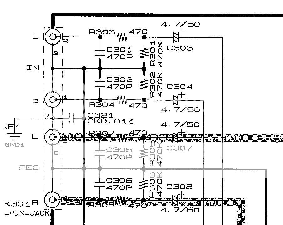
Below is a plan of the input (first 2) and output (last 2) stages of a preamp. I would like to understand their cutoff frequencies and see if any components may be better replaced.
I know the formula 1 / (2 x pi x R x C) but I am not sure about the values to be used here. Doesn't help that I am a nurse
Questions:
1. Let's just take the top L input. Am I right to understand that C303 and R301 form the high pass filter, and R303 and C301 form the low pass filter? If so, I can just plug in the values into the formula myself. The problem is that I came up with quite illogical numbers doing so.
2. If I can understand the appropriate numbers to be plugged into the formula, I should be able to understand the operational characteristics better.
But if you have any suggestions on how I can improve (or remove) these filters, I will be very grateful.
Thanks!!
Jenn
Been lurking and furiously reading for a while, before summoning the courage to ask here
Below is a plan of the input (first 2) and output (last 2) stages of a preamp. I would like to understand their cutoff frequencies and see if any components may be better replaced.
I know the formula 1 / (2 x pi x R x C) but I am not sure about the values to be used here. Doesn't help that I am a nurse
Questions:
1. Let's just take the top L input. Am I right to understand that C303 and R301 form the high pass filter, and R303 and C301 form the low pass filter? If so, I can just plug in the values into the formula myself. The problem is that I came up with quite illogical numbers doing so.
2. If I can understand the appropriate numbers to be plugged into the formula, I should be able to understand the operational characteristics better.
But if you have any suggestions on how I can improve (or remove) these filters, I will be very grateful.
Thanks!!
Jenn

I can understand your confusion. The circuit excerpt you show does not provide enough information to calculate turnover frequencies.
C301 forms a low pass filter with whatever is the source resistance before it - but that is off the circuit in the source. I'm not sure why R303 comes after it, unless their aim is to prevent RF escaping from the circuit via an input.
C303 forms a high pass filter with whatever load resistance comes after it - but that is in the rest of the circuit which you have not shown.

I put C301/302 directly across the RCA input socket. The 47pF on very short leads to give a reasonable chance of attenuation the VHF, before it starts traveling along the wires and radiating into other parts of the circuit.
Putting 470pF on the PCB AFTER the wiring is too late.
Recently I went further an used an XLR with both differential and common mode filtering (still 47pF, now 3off for each channel) on the input socket for an unbalanced input.
Putting 470pF on the PCB AFTER the wiring is too late.
Recently I went further an used an XLR with both differential and common mode filtering (still 47pF, now 3off for each channel) on the input socket for an unbalanced input.
You might find this helpful to confirm any calculations you do.
calculators for electronic circuit design
Daves pretty much covered it all really. The 470pf is an "unknown". Imagine an old "DIN" standard cassette deck from the 70's and 80's. Supoose it had an output impedance of 40K. 40K and 470pf would be 3db down at only 8.5Khz. No good.
I would suggest those 470pf caps could probably be usefully removed or lowered in value together with another series resistance to define a more definite roll off point.
The 4.7 uf cap will define the low frequency roll off. If you increased that cap to say 10uf you would also have to look at all the other similar caps in the chain.
One real area to improve could be the output muting which uses four paralled transistors (bottom left). Replacing these with a single pair of FET's could be worthwhile as long as the control voltages are suitable.
Thanks for the helpful opinions. If I understand correctly and focus on improving the I/O stages for now, a more logical configuration may be to:
1. Remove C301.
2. Remove R303 and jumper across.
3. Replace C303 with a 0.22uf for a cutoff at 15hz.
Did I understand the principles correctly?
Very grateful for your help. Thanks!
1. Remove C301.
2. Remove R303 and jumper across.
3. Replace C303 with a 0.22uf for a cutoff at 15hz.
Did I understand the principles correctly?
Very grateful for your help. Thanks!
Thanks for the helpful opinions. If I understand correctly and focus on improving the I/O stages for now, a more logical configuration may be to:
1. Remove C301.
You could remove C301. If you found that RF interference was a problem (if you live under a transmitter) then you might have to think again and perhaps tailor something more suitable.
2. Remove R303 and jumper across.
I wouldn't do that. Despite its low value it affords considerable protection against any transients that may occur connecting leads, something that's important with electronic input switching. The audible penalties of a resistor that low are to all intents and purposes nil.
3. Replace C303 with a 0.22uf for a cutoff at 15hz.
I'm not sure how you've come up with that
0.22uf and 15Hz would need the resistive part (to the right of C303) to be around 48KC303 is a 4.7 uf. The lower cut-off frequency is actually determined by the (unknown) input impedance of the preamp circuitry to the right of the cap. Making the cap larger would lower that value further but as mentioned earlier, it would need a detailed look at all the circuitry.
- Status
- This old topic is closed. If you want to reopen this topic, contact a moderator using the "Report Post" button.
- Home
- Source & Line
- Analog Line Level
- Any suggestions to improve these output and input filters?