Hi DIYAudioers
I hope my question is appropriate for this forum and this subsection - if not, please delete.
I have one of these preamps that appears to be unwell. I have no electronics experience, and the technician I took it to, says it seems to be impossible to disassemble so that the bottom of the pcb is visible. The top and side covers seem to be a single folded sheet which is easily removable. However, the rest of the case (bottom with front and back panels) is also a single folded sheet, with various pcb-mounted switches and jacks attached to it. It might be possible to rip components out of the board. but would be difficult to solder replacements into position. I have been assured that this will make it impossible to isolate the fault, without major surgery to the case.
So.....are there any arcane tips or tricks, magical incantations, secret levers or switches that could unlock this ancient and mystical device? Or was it designed to be disposable?
Even if we were able to expose the entrails, is there a service manual or schematic available that could be used to interpret the omens and portents thus revealed?
I seem to recall that it was quite fine-sounding, when it was working, but is it actually worth the struggle, perhaps removing the front (with glued-on faceplate) and rear panels with an angle-grinder?
Also....it has a 2-pin 'wall-wart/power-brick' box with captive lead. This has half a faded sticker which seems to mention a number of voltages, i.e. 220/240 V AC and 15-0-15 V AC. Does this mean the brick is merely a transformer? What could I replace it with? (One of the mains plug pins is wobbly)
Is 15-0-15 V AC the same as 30VCT? They seem quite rare.
The label says something like
CAUTION
Do not tamper with this unit. Lethal voltages internally.
?5VA Transformer (15? 115? 75? probably 15VA)
For? use only with John Bowers Active Control Unit 1
?ary : 220/240 V AC
?ary : 15-0-15V AC (I'm almost certain the 3rd number is 15)
The rest is illegible/missing.
Can anyone please help with documents, solid info, pointers or experience?
I would be eternally in your debt for at least 5 minutes.
Thanks and Regards
Paul
Maybe post some pictures of it internally for a start. Unless its been welded together disassembly should (famous last words) be straightforward.
The PSU could be a 15/0/15 Vac tranny. Have you done any measurements on it to see what voltages emerge ?
The PSU could be a 15/0/15 Vac tranny. Have you done any measurements on it to see what voltages emerge ?
Hi, thanks for the response. Struggling a bit to load pictures, looks like the process crashed while trying to create an album on diyaudio, and loading pictures into it.
oops....just saw the "Manage attachments" button....and the "max filesize" section....some resizing needed.
I don't know how to measure the output of the power supply. It has 3 wires, red, blue and yellow. Should I just set my DMM to ACV 750 and expect 15V between..er...red and blue, and between yellow and blue?
Should I disconnect the power supply from the pre while doing this? It will involve some desoldering, it's hardwired.
Attachments
-
 jbacu_from_the_back_02.JPG390.2 KB · Views: 539
 -
 jbacu_front_panel__stuff_to_remove_02.jpeg370.9 KB · Views: 407
 -
 jbacu_bottom_with_front_and_side_02.JPG309.4 KB · Views: 390
 -
 jbacu_from_the_front_02.JPG267.8 KB · Views: 452
 -
 jbacu_back_panel_stuff_to_remove_01.JPG337.6 KB · Views: 382
 -
 jbacu_bottom_with_back_and_side_01.JPG277.7 KB · Views: 192
It looks very straightforward... if it needs pulling apart we can come to that later.
Measure initially with all the wires intact.
From what I can make out there appears to be 3 pins on the PCB (near the on/off switch) marked as 0, 15 ?? and 15 with a yellow wire going to 0 and two blue wires to the pins marked 15.
So first test... and I can't see any rectifiers (diodes) near this area so we have to test to see if either AC or DC is present.
Set your meter to an AC volts range (750 range is OK to start) and measure between the yellow to each of the blue wires on those pins. Keep the black lead of the meter on the yellow pin for these tests. If its AC you will see around 15 volts on each blue pin with respect to the yellow.
If you don't measure anything or the readings are low then we see if DC is present.
Set your meter to a DC volts range (say 100 volt range) and again measure between the yellow to each of the blue wires on those pins. Keep the black lead of the meter on the yellow pin for these tests. If its DC I would expect (from the markings) a reading of plus 15 or so volts on one pin and minus 15 on the other.
So that's the first step. Is the unit dead ? I don't think you mentioned what the actual fault was.
Also, can you make out the device type markings of those two black, 8 legged integrated circuits behind the volume control. If we know the type we can identify the supply pins and see whats what 🙂
Hi
Thanks for your interest. This must be like playing multiple games of blindfolded 3D chess via snail-mail.
Some responses :
the 2 arachnids seem to bear the legends "NE5534AN" and "S 8419". There is some white script on the PCB near them
I think the relevant bits are IC2R for 1 and IC2L for the other. (There's also a C27R and C27L, close by, I hope that refers to
the adjacent little orange M&M thing.)
There are 4 other arachnids, all are inscribed with "M340" and "LF353N".
Looking from the front....LHS is LeftHandSide, RHS is RightHandSide
The 'power' lead from the power supply has 3 wires, a red, and blue and a yellow.
The red goes (via the On/Off switch) to 15V closest to the middle of the device (a.k.a. RHS 15V)
The blue goes (via the On/Off switch) to 15V closest to the edge of the device (a.k.a. LHS 15V)
The yellow goes direct to 0V.
DMM is MajorTech MT845 with a new, freshly changed battery
200 ACV:
Yellow to LHS '15V' 3.8V sometimes 3.9V
Yellow to RHS '15V' 3.5V sometimes 3.8V
20 DCV:
Yellow to LHS '15V' -9.15V (negative 9.15V ??)
Yellow to RHS '15V' -9.2V (negative 9.2V ??)
I don't know how trustworthy that '-' minus sign is....even just switched on, with no measuring happening, the '-' comes and goes(-0.00 to 0.00)
The voltages I measure, seem to fluctuate.....I'm assuming the 'highest' number (disregarding the '-') is the most accurate, with me making better contact. I am scared of slipping off the solder and spearing vulnerable bits with the probes.
The (2-pin) power brick has a loose(ish) pin....and, being 2-pin, it can take a little while to settle it firmly in the socket.
The umbilical has a break which was messily soldered up long ago(not by me). Does it seem as if it is worth tidying it up?
Attachments

Your meter flipping between - and + when showing approx. zero (0.00) is normal.
The NE5534 and LF353 are "opamps" and have their supplies on pin 4 and pin 8.
The readings from the power supply seem odd (and it may well be a faulty PSU) so the next check is to put your meter on the 20 volts DC range and measure between ground (use that big knurled nut on the rear panel) and pins 4 and pins 8 on those opamps. Keep the negative lead of the meter on the ground point.
What voltage do you measure on pin 8. What voltage on pin 4 ?
(those voltages from the PSU look wrong because if it were AC from the adapter then 3.9 volts AC is far too low to work with, and if its DC then there should be a plus and a minus rail with respect to the yellow. And your measuring two negative voltages. Everything points to the PSU being faulty at the moment)
I looked up the pins here http://circuits.datasheetdir.com/25/NATIONAL-NE5534-pinout.jpg
and got this in the 20 DCV range, for both opamps - there is some unsteadiness, perhaps due to my trembling hand:
Pin 4: -14.1V <> -14.3V
Pin 8 + 2.6V <> + 2.7V
OK, some random fiddling and slight change in symptoms.
Turning the power brick over in my hands, seeking an attack vector, I noticed what appeared to be a movement of a weight inside. I would not be surprised if it turned out to be the alien larva that secretes the magic smoke stirring in repose, or perhaps a loosely mounted small transformer. Pure conjecture, of course. Deciding to pursue the loose transformer theory, I runned the power strip upside down and pressed it down on the power brick, which lay on its back with the plug pins pointing up. I then did the measurements over.
0V 15V 15V wires:
----------------
200 ACV:
Yellow to LHS '15V' +15.2V
Yellow to RHS '15V' +15.2V
20 DCV:
Yellow to LHS '15V' -0.14V approx
Yellow to RHS '15V' -0.14V approx
NE5534AN" and "S 8419" Opamps :
------------------------------
20 DCV range, for both opamps - there is some unsteadiness, perhaps due to my trembling hand:
Pin 4: -14.1V <> -14.2V
Pin 8 +11.8V <> +11.9V (LHS seems slightly higher)
While moving power strip and brick into position, the pre (with nothing else connected) sometimes makes a gentle but disturbing 'tick' sound, perhaps as bits jostle for position inside the brick. However, once everything does settle, the pre is silent.
Interestingly enough.....the left channel on the pre now seems to work. The right channel is still silent. Except......
Both left and right 'pre-out' channels give the standard horrible 'missing earth' shout through the speakers, if the pre-to-power
plugs are re-arranged by someone too lazy to switch off the power amp. If the RHS pre-out is connected to the power amp, there is no sound...except...if I touch the multimeter probe to one of the copper bars in the pre-out internal chassis-mount assembly AND the one of the copper bars in the adjacent 'tape-rec' internal chassis-mount assembly, then I get a faint musical signal through the speaker. This signal does not seem to be affected by the volume control.
I tried to show this bridging with a red line....please ignore the blue wire which refuses to move. I'm guessing the bridge is Pre-out's Right channel
hot to Tape-rec left channel hot. Just a guess, though.
So...does this support your theory that the power brick is unwell? I'm scared to move it....
Is it safe to hypothesize that I could benefit from a new 15 - 0 - 15 ACV brick? Is there anything special I should look out for in seeking a replacement?
Or is there still a concern that there should be a -15V somewhere? (I interpret your earlier comments to mean that this would be only if the brick was supplying DC)
I have the idea that the 'missing channel' problem is why I stopped using the pre, long ago. Will I need access to the bottom of the PCB to fix this? I suspect there's no happy ending here, if that's the case.
Attachments

There's a lot going on with this one 🙂 There may be more than one problem too.
Something loose in the PSU isn't normal so that needs looking at. Is it a glued together thing or does it come apart ? Any screws might be under stickers etc
I think the PSU has to be the first line of attack. From what you have shown you should be seeing -/+ 15 volts from the PSU and you are not... but it sounds like there are other problems too.
The 5534 opamps should have "equal and opposite" supplies. It seems as though 15 volts is the voltage this preamp runs on and so you should see plus 15 on pin 8 and minus 15 on pin 4 measured with respect to ground.
The PSU isn't an off the shelf item as it appears to be a -/+15 volt unit (that's DC).
Thanks for the feedback, sorry about the delay, been bit distracted recently.. You say the brick is broken, but....is this best-case measurement not a sign that sometimes the brick is working OK?
0V 15V 15V wires:
----------------
200 ACV:
Yellow to LHS '15V' +15.2V
Yellow to RHS '15V' +15.2V
OK, anyway, trying to open the brick. It was obviously sealed by someone who hates me. It seems to have a bottom plate with a top shell, both plastic. The bottom plate has 3 'spots' which might be screw-holes filled with plastic, like one might use plastic wood to the heads of woodscrews in furniture.
I used a grinding bit attached to an electric drill to try to get to one of the screws - looks like I found one. Bit late to be operating a drill now - hope to get to the others later this week.
Attachments


Lets try and get a handle on what is going on here because some of the readings seem very variable.
Your saying with the meter on 200Vac range that you measure 15 volts between the yellow lead (using that lead as the common) and the other two from the brick. Those readings sound on the face of it reasonable, but are different to the 3.8/3.9 volts reported in post #5. Have we an intermittent problem with the brick or not ?
Lets say that as long as you can read 15 volts from the brick, then we'll say that its working "at that moment in time" and we can try a different approach.
Do you see the two 3 legged devices (that have metal tabs on them) located between those four large blue electrolytic capacitors. They look like voltage regulators.
Can you make out the type numbers on them ? If we know the devices we can see if the voltages are correct or not. The regulators could be something like 7812, 7912 or LM317 and LM337 as an example.
Yes, I am sure there is an intermittent problem with the brick. There seems to be something loose inside it.
The 'best' measurements that I got were these:
0V 15V 15V wires:
----------------
200 ACV:
Yellow to LHS '15V' +15.2V
Yellow to RHS '15V' +15.2V
Without moving the brick, I then got these measurements for the 8-legged crawlies:
NE5534AN" and "S 8419" Opamps :
------------------------------
20 DCV range, for both opamps -
Pin 4: -14.1V <> -14.2V
Pin 8 +11.8V <> +11.9V (LHS seems slightly higher)
I did get some other measurements, but.......By 'best', I mean 'most representative of what the brick can do when the loose bits fall more or less into the positions into which they were inserted by their maker'. I have no evidence to support this assertion; perhaps the other (~9V) numbers were 'best', but this seems unlikely.
The terms REG1 and REG2 are printed on the PCB, near these 2 chips.
REG1 is closer to, and parallel to, the back panel:
7815
UC8420
KOREA
REG2 is closer to, and perpendicular to, the front panel:
7915
UC8419
KOREA
The 7815 and 7915 are standard voltage regulators and I would have expected the NE5534 etc to run on the full output of these which should be very very close to the stated 15 volts.
This is what I'm thinking...... the PSU is faulty, particularly as you say something is loose. Are the voltage readings really a good indication of what is going on... by that I mean that a definitive check would now involve the use of an oscilloscope to see if the DC voltages are "clean". Could the loose part in the PSU be a reservoir cap ? That could give all sorts of misleading info.
I think opening the PSU has to be the next step and to see what is going on in there.
I have completed my desecration of a British audio sacred site by opening the brick. It seems the 3 retaining screws were covered by plugs of some sort of plastic formulated from Mr Bowers' hatred of me. Anyway, inside we seem to have a transformer and another component - could it be a fuse? I don't see anything else electronic inside, other than wires.
BELOW:
Looking at the bottom (the side closest to the power pins), it seems a plastic post or pin of some sort broke off (it was lying inside the case).
I don't know if this is an old injury, or was caused by my fiddling. I hope it's not an issue.
BELOW:
Looking at the top, on the side that receives live AC from the wall (the primary side?) , it seems there is a component with some alphanumerics on the side "UM1" or "UM1" "100 degrees C" and "3A 250V" (it looks like it might be "3A 250V ~" - perhaps that little squiggle is an AC symbol) and "X100"
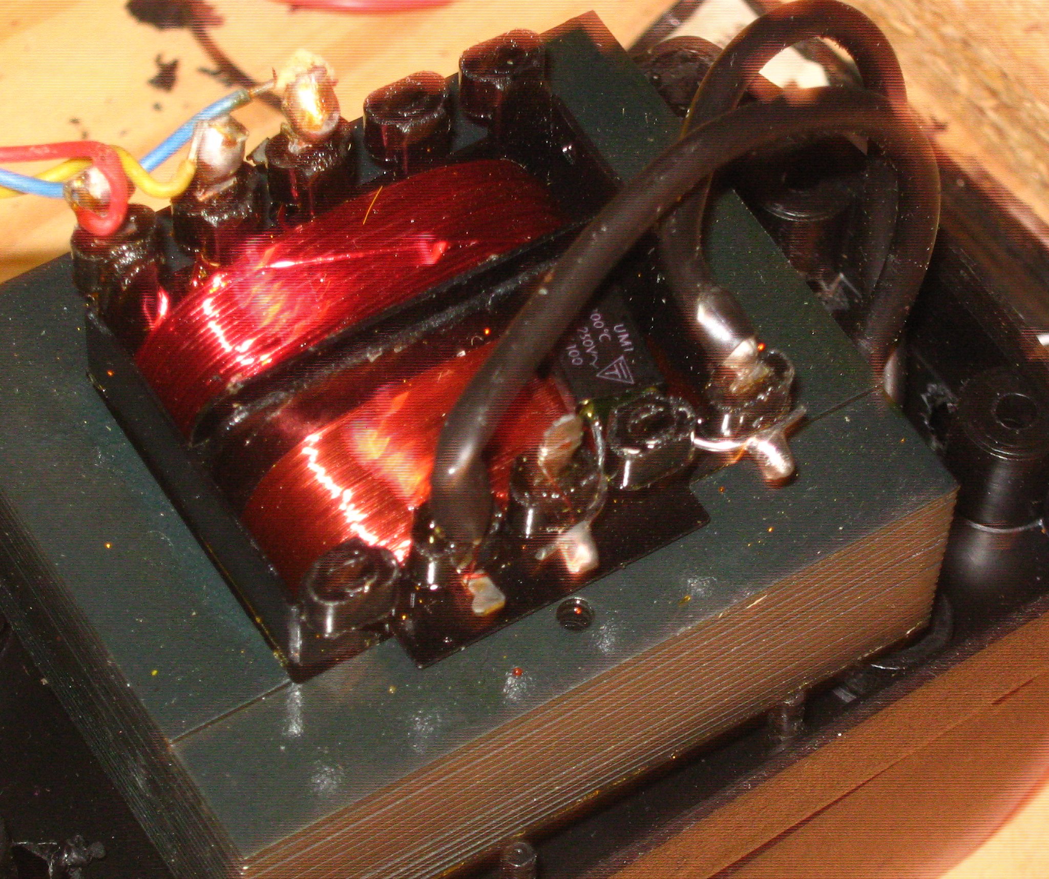
BELOW:
This I assume is the secondary side, with the 2 wires Red, Blue and Yellow that connect to the pre.
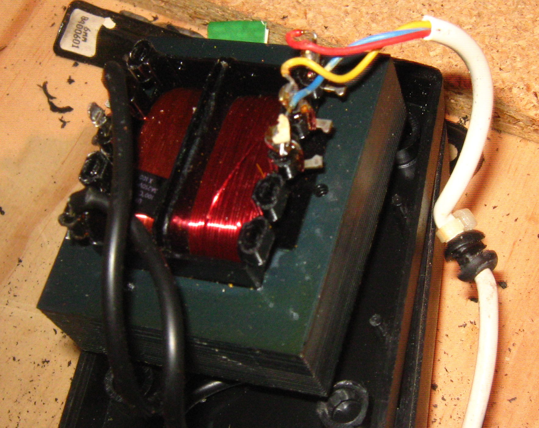
Do these pictures speak to you? Other than saying "I wish he'd get a better camera and learn how to use it"
I took a deep breath and plugged the open transformer into my power strip and measured it. The primary has 228V between the 2 wires (on 750ACV range). The secondary wires have a little over 15V (200 ACV range) which seems encouraging. The 15-0-15 PCB
points seem to be giving me 24V(Yellow to Blue) and 31V (Red to Blue). This seems a bit odd, have never seen this before....it's late and I am nervous about that open trafo, so I don't trust my measurements - will put away the grown-up toys for now.
I hope the pictures (such as they are) come through OK - they seem either too big or too small.
BELOW:
Looking at the bottom (the side closest to the power pins), it seems a plastic post or pin of some sort broke off (it was lying inside the case).
I don't know if this is an old injury, or was caused by my fiddling. I hope it's not an issue.
BELOW:
Looking at the top, on the side that receives live AC from the wall (the primary side?) , it seems there is a component with some alphanumerics on the side "UM1" or "UM1" "100 degrees C" and "3A 250V" (it looks like it might be "3A 250V ~" - perhaps that little squiggle is an AC symbol) and "X100"
BELOW:
This I assume is the secondary side, with the 2 wires Red, Blue and Yellow that connect to the pre.
Do these pictures speak to you? Other than saying "I wish he'd get a better camera and learn how to use it"
I took a deep breath and plugged the open transformer into my power strip and measured it. The primary has 228V between the 2 wires (on 750ACV range). The secondary wires have a little over 15V (200 ACV range) which seems encouraging. The 15-0-15 PCB
points seem to be giving me 24V(Yellow to Blue) and 31V (Red to Blue). This seems a bit odd, have never seen this before....it's late and I am nervous about that open trafo, so I don't trust my measurements - will put away the grown-up toys for now.
I hope the pictures (such as they are) come through OK - they seem either too big or too small.
So it really is AC coming from the brick. There must be a diode bridge unsighted in all the other pictures of the main unit. That's one thing that has kept puzzling me. The other component is a thermal fuse to protect against overheating. Sounds like 100C and 3 amp rating
Its normal for secondary voltages from a small transformer to be a lot higher when unloaded.
Anyhow, we have to measure the exact voltages on all 6 legs of those regulators, the 78 and 7915. Measure from ground (negative meter lead on ground for all). Notice how the pinouts are different for the negative 7915.
Expected readings would be plus 15 volts and negative 15 volts respectively for the 7815 and 7915. The inputs voltage should be at least 19 volts or higher (all DC). The ground pin should be at zero volts but measure it to confirm.
Attachments


Hi
I am have been unable to get the 3 '0V 15V 15V' wires going into the PCB to give me 15 volts again. I am reluctant to toss the transformer around like I did with the black box, as it is now exposed. It seems that the transformer secondary happily gives 15VAC from the red and blue wires, measured against the yellow, but when I measure the 3 '0V 15V 15V' wires at the PCB, they are 3.5V - 3.7V AC. With those results, I am not sure it is worth trying to measure anything further?
I did notice this stain at the base of one of the 4 biggest capacitors - it's the one closest to the power switch.

Could this be enough to cause all the problems? Or at least, is this something that will have to be fixed before it is worthwhile to continue testing?
Also, when you mentioned the words 'diode bridge', I thought of these things.

There are 3 of these little black cylinders with the silver collar. They are labelled D1, D2 and D3 on the board.
There is also a hockey puck-shaped thing labelled BR1. They are all very close to the power switch , the 4 biggest caps, and the '0V 15V 15V' landing. I tried to indicate D1 D2 and D3 with red lines.
So...regarding the possible cap leak - Do 'we' need an operation?
I still don't see how to get the board out without an angle grinder.
I am have been unable to get the 3 '0V 15V 15V' wires going into the PCB to give me 15 volts again. I am reluctant to toss the transformer around like I did with the black box, as it is now exposed. It seems that the transformer secondary happily gives 15VAC from the red and blue wires, measured against the yellow, but when I measure the 3 '0V 15V 15V' wires at the PCB, they are 3.5V - 3.7V AC. With those results, I am not sure it is worth trying to measure anything further?
I did notice this stain at the base of one of the 4 biggest capacitors - it's the one closest to the power switch.
Could this be enough to cause all the problems? Or at least, is this something that will have to be fixed before it is worthwhile to continue testing?
Also, when you mentioned the words 'diode bridge', I thought of these things.
There are 3 of these little black cylinders with the silver collar. They are labelled D1, D2 and D3 on the board.
There is also a hockey puck-shaped thing labelled BR1. They are all very close to the power switch , the 4 biggest caps, and the '0V 15V 15V' landing. I tried to indicate D1 D2 and D3 with red lines.
So...regarding the possible cap leak - Do 'we' need an operation?
I still don't see how to get the board out without an angle grinder.
Your last picture does indeed show the "missing" diodes and bridge rectifier I mentioned earlier.
So it sounds like you have some breaks on the wires from the tranny... that's an easy fix... new wire. Or you could try shortening it, the breaks are probably where it is stressed at those cable grommets.
The cap may or may not be a problem. Hard to say just from the picture. Sometimes they have glue put on them on them to help with mechanical stability.
Fix the wire first, then we can see what is happening.
Hi
I think I may have the same problem....and I suspect its the BR1 bridge rectifier.
I have 16VAC going in and +15.9VDC coming out of one terminal and only -7.4VDC coming out of the other!
Similarly I have 15.3VDC at pin 4 on the opamps and only 6.5VDC on pin 8
From the regulators I have +15.3VDC from 7915 and 6.00VDC from 7815.
All this seems to me to suggest the rectifier.
Also it seems the 12 VDC relay is not engaging an so shorting the output.... probably because it only has 7.53VDC going to it! The non-relay output (tape rec) outputs signal fine...but of course no volume control. Difficult when you are feeding active speakers!!
Is it worth a go replacing??
please let me know
Plus 15 volts from a negative regulator suggests something really basic.
I wouldn't suspect the bridge at this stage, the voltages are correct... 16vac in and 23 out (15.9 + 7.4).
What seems in error is the 0 volt reference. Without seeing a circuit its all guesswork but with the unit in front of you it should be easy to see whats going on. Check if the bridge output goes to a single reservoir cap or whether its a dual split supply with zero volts taken from the junction of two caps. Or, does it use a virtual earth ?
seems to be a split supply with one bridge output goes the capes with zero taken between the two caps
the other bridge supply goes to two diodes and a smaller cap to field the 7.4
the other bridge supply goes to two diodes and a smaller cap to field the 7.4
The junction of the first two caps off the rectifier we assume is ground (check it). If so then the measured voltage should be equal on both caps. What happens after that point depends on the circuit but as a basic first step those two voltages across those first two caps have to be equal.
- Status
- Not open for further replies.
- Home
- Source & Line
- Analog Line Level
- John Bowers Active Control Unit preamp: Info sought