I need to tap an existing mixer circuit to obtain output for use in a second audio mixer circuit. I'm concerned about crossover between the two and plan to install a unity gain non inverting op amp (rigged single supply) as a buffer to prevent it. (Tapped audio signal from circuit 1 through the buffer to circuit 2 for mixing). Neither is high frequency, just mixed audio signal out of a couple of radios and another signal from a SM2166 mic pre-amp.
Is anything special required for this or would something basic like a UA741 work well enough? My supply is 5V.
All suggestions and or critique is welcome.
Is anything special required for this or would something basic like a UA741 work well enough? My supply is 5V.
All suggestions and or critique is welcome.
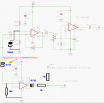
Here is the schematic;

Everything except the OP113 exists now on a double sided SMD board about the size of a 9V battery. It works well however I wasn't thinking of recording the radio traffic when I designed it. The digital pots permit volume control remotely from a very small panel with 4 buttons and a transmitter selector worn on the chest (the main box is stored with the radios on the back and is inaccessible).
The plan for this version is to output the mixed radio audio via the OP113 rigged as a unity gain follower which will then be again mixed with a signal from a condenser mic and SSM2166 mic pre-amp via a single supply op amp. This new mix will be injected into a video recorder. (The OP113 was selected because it's unity gain stable on single supply).
The idea is to eliminate any chance of crossover between the two mixer channels.
Comments?
Thanks for the suggestion but I think I'll be using an OPA134 for the job and yeah the NE5532 is a dual channel chip.
Those are good chips but not on 5 Volts. I would never consider a mic preamp with such limited headroom. Limiters are useful but when _I_ want to use them, not because of limited dynamics due to no power.
The OPA134 claims it can reach within a Volt of the rails. On a 5 V supply that's 3 Vp-p - pretty limited. The 5532 recommends +/- 3V power minimum.
G²
I do have a 9 volt rail in this project so if necessary I can up the supply a bit.
Thanks for the suggestions. I certainly appreciate the input. Coupling caps of course, don't know why I left them out and I understand the balancing resistors on the buffer output side but why 10k off the input to ground? Also the 100 uF cap on the voltage divider? Stability?
@ Copper Dog
To provide an input impedance/resistance. The resistance "could" be higher, it depends on the Actual output impedance/resistance of the preceeding stage. As i havn't played with those attenuators, i'm not sure what the Exact value is. I made a guess @ 10k being "probably" ok to match it. It's usual to make the input impedance around 10 times higher though.
In a way, but also to reduce power supply noise getting in.
Re the Bipolar cap.
I advocated using one of those as i'm not sure how much DC offset, if any, from the attenuators there is, as the volume is varied ? If you use 2 x electrolytics in series as a Bipolar, make SURE they are connected + to + or - to -
why 10k off the input to ground?
To provide an input impedance/resistance. The resistance "could" be higher, it depends on the Actual output impedance/resistance of the preceeding stage. As i havn't played with those attenuators, i'm not sure what the Exact value is. I made a guess @ 10k being "probably" ok to match it. It's usual to make the input impedance around 10 times higher though.
Also the 100 uF cap on the voltage divider? Stability?
In a way, but also to reduce power supply noise getting in.
Re the Bipolar cap.
I advocated using one of those as i'm not sure how much DC offset, if any, from the attenuators there is, as the volume is varied ? If you use 2 x electrolytics in series as a Bipolar, make SURE they are connected + to + or - to -
I realised the digital pots are 10K, but wasn't sure whether the outputs were internally buffered, or not. I guess not ?
I noticed the caps but thanks for pointing it out.
The DS1809 output (pin RW) is connected directly to a multiplexer. None of the data sheets refer to any buffering on the output other than that. Total wiper resistance is stated at 400 ohm.
Whats your opinion on running this buffer at 5 volts? I was hoping to keep the entire second channel at 5V. The mic pre amp (SSM2166) is designed for that and I was going to select a mixing op amp for the same voltage rating. The OP113 is there to buffer not amplify anything and the mixed ouput will be injected into a camera not driving a speaker. (I have no idea what the input impedence of a typical helmet cam is).
I could use an OP413 and wire one channel for the buffer, another as a mixer and another to amp the mix.
Last edited:
Whats your opinion on running this buffer at 5 volts?
As the PDF for the SSM2166 states this,
ABSOLUTE MAXIMUM RATINGS Supply Voltage 10 V
9 volts should be fine for ALL the IC's
")
I was going to select a mixing op amp
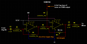
An OpAmp mixer would be best for the SSM2166 & other output. The correct way to do it is by using the OpAmp in Inverting mode. However, doing that means whatever is fed in comes out inverted. If that's not a problem, then fine. If it is, use 2 x OpAmps, or a Dual, inverted in series, to bring the signals back in phase. Here's a suggestion.
Attachments
@ Copper Dog
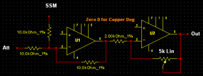
It's been a very hectic day for me, as amongst other things i had to sort someones PC out that had a Very serious Malware infection ! I did want to help you out so posted my last screenie. Now that the PC is sorted, i've had more time to look over things. I notice that, even though my last circuit should work just fine, the output is still phase reversed. My bad ! I didn't want to leave it as is, so i've made another one for you
The other components/connections are the same.
Attachments
But I also see what you mean. The input from the Mic would be inverted while the radio audio wouldn't be at the output. Not sure if this would be a problem on the video recording or not. It might actually help in editing the videos if the Mic sound appears inverted in the audio track. I don't know enough about recording to determine if this would pose a problem.
I like the first idea since it puts a buffer in between the Mic output and the input from the radios.
I can see what you're thinking. Actually though, as both OPAmps are in inverting mode, they appear as buffers to the inputs, in both/all cases.
Sounds like you're busy.
Yes, but i like to try & get things right !
Thanks for the time on this.
Pleasure
But I also see what you mean. The input from the Mic would be inverted while the radio audio wouldn't be at the output.
Exactly.
Not sure if this would be a problem on the video recording or not. It might actually help in editing the videos if the Mic sound appears inverted in the audio track. I don't know enough about recording to determine if this would pose a problem.
IMO it would be better if everythings in phase. If you're using for eg a digital PC video/sound editor, you could invert the audio & see what difference it makes. If you're not then as i just suggested, but it's your call.
Is your main Mixer stereo, & the video recorder ? If so how are you propsing to connect everything together. As your circuits & mine are MONO.
By the way, the 5k Pot can be a PreSet PCB type.
No the main circuit Is a mono channel as well. It outputs the mixed radio audios to a single shoulder speaker microphone. I just want to take the radio audio and record it on a video. Unfortunately, jacking into the camera disconnects the cameras own microphone hence the separate Mic input. I'm trying to avoid any feedback to the radio channel. I don't want to hear what the Mic picks up come out the speaker.
- Status
- This old topic is closed. If you want to reopen this topic, contact a moderator using the "Report Post" button.
- Home
- Source & Line
- Analog Line Level
- Preventing crossover between mixers