No.
the intervening ground(Returns) in the HDMI cable are mandatory for the proper low impedance of the signal pairs. The cable MUST operate at VHF and at these VHF frequencies the IMPEDANCE of the signal pair is vitally important. Closeness of the Signal HOT to Signal Return determines the inductance of the Signal Pair. That inductance must be low to preserve the digital rise/fall times.
the intervening ground(Returns) in the HDMI cable are mandatory for the proper low impedance of the signal pairs. The cable MUST operate at VHF and at these VHF frequencies the IMPEDANCE of the signal pair is vitally important. Closeness of the Signal HOT to Signal Return determines the inductance of the Signal Pair. That inductance must be low to preserve the digital rise/fall times.
Here is another thread on HDMI ground loops:
http://www.diyaudio.com/forums/digital-line-level/211927-how-break-possible-hdmi-ground-loops.html
AndrewT, I see your point about returns in each signal pair - they are designed for a specific twist rate, and a certain thickness so as not to have phase errors at the bit stream frequencies. Screwing around with their shields might not be productive. I wonder if those 4 HDMI shields and 1 earth return have low enough impedance at audio frequencies to even pass audible ground loop currents.
I think I'll interrupt only the outer earth/ground shield at one end of each HDMI cable, and leave the signal bundle alone. Pins 1-19 I will look at as one signal lead. After connecting the whole system, I will measure AC voltage at the speaker outputs with and then without the HDMI cables to see it there is any difference.
http://www.hottconsultants.com/pdf_files/aes-2007.pdf
Designing for Interference-free Audio System Components
A Practical Interference Free Audio System (Part 2)
Bonding Cable Shields at Both Ends to Reduce Noise
We have to assemble systems in the non diy world where you have to have a direct PE connection, no circuitry between PE and the equipment.
Cables have to be connected at BOTH ends for shielding, otherwise it doesn't shield, especially at RF frequencies.
Quite often the problem is the lower frequencies (the hum) following a path you didn't know was there, as they tend to follow a different path to the HF stuff.
Thanks, marce, I'm reading Ott
http://www.hottconsultants.com/pdf_files/aes-2007.pdf
and in slide 22 he answers my question: How do I get my single-end coax cable to act as if the shield is connected at both ends at the RF spectrum so it doesn't act like an antenna, and at the same time have an unconnected shield at low audio frequencies? Answer: Hybrid grounding.
Partial Ground Lift
Looking around some more, a cap alone would decrease shield current all the way down in frequency at 6 db per octave. In "Ground Lift"
Groundloop problem solving: Ground lift circuits
Tomi Engdahl recommends a cap for single end lines like Ott:
. Signal --------------------- Signal
. Ground -------||----------- Ground
................... 10 nF
In the same article Engdahl adds a resistor in parallel for balanced connections:
Partial ground lift with RFI filtering for balanced XLR connectors
...............+--||--+
...............| _____|
...1 ------+-|____|+--- 1
.................100 ohm
...2 ------------------ 2
...3 ------------------ 3
Couldn't I do this at the far end of each single-end connection between chassis?
..Signal -------------------- Signal
......................10 nF
..................+---||---+
..................|.______.|
..Ground ----+-|____|-+--- Ground
....................100 ohm
-Assuming, of course, my 4 AWG PEC also runs between them?
Assuming each input or load is 25K ohms, and I would like high pass with -3db at 200KHz, C=1/(2pi*f*R)=31.8 pF, or 32pF, then for the far end of each coax:
..Signal -------------------- Signal
......................32 pF
..................+---||---+
..................|. _____. |
..Ground ----+-|____|-+--- Ground
....................200 ohm
This would allow current to flow through the shields at RFI frequencies, but very little to flow at 60Hz or 120Hz. Most all of the current would go through the big fat parallel earth connection.
What do you guys think - Is there any way this setup could affect the audible spectrum? Would it be worth it to get high-quality caps at these small values, maybe like they used to use to adjust capacitance of phono cartridges?
Neutrik NC3MXX-EMC
Arguing with myself again, but here is the Neutrik NC3MXX-EMC balanced connector, which uses a coaxial cap of 4pF or less (along with an inductor):
Mine will be cruder, a cap and a resistor on the receiving end of each unbalanced connection.
Arguing with myself again, but here is the Neutrik NC3MXX-EMC balanced connector, which uses a coaxial cap of 4pF or less (along with an inductor):
Mine will be cruder, a cap and a resistor on the receiving end of each unbalanced connection.
Attachments
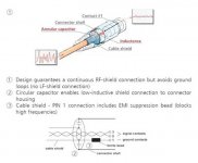
Inputs "Above Ground"
Update: Okay, now I have a 4 gauge common earth/ground running near every piece of gear, and there is a 16 gauge wire soldered to the big cable with a spade lug on each end, for each chassis connection point. This will be the one and only safety ground and signal return path. All shields will be 200 ohms up to around 200khz.
Concern: To make this work I will have to make sure the shield connections to my Adcom power amps are connected as one. But these inputs are "above ground," and insulated from the metal box. Before I short these two points, is anyone aware of anything bad that could happen downstream?
You know what? I'm going to go ahead and test it with jumpers from shield to chassis ground. Check for DC, hum, etc. In the manual they advise not to install in a rack with the chassis bonded together, to avoid ground loops, and of course that's what I'm doing, except with one and only one ground/earth. I'll try it with and without and see which has less AC at the output terminals.
Something like this? (see below)Update: Okay, now I have a 4 gauge common earth/ground running near every piece of gear, and there is a 16 gauge wire soldered to the big cable with a spade lug on each end, for each chassis connection point.
What does this 200 Ohms mean?All shields will be 200 ohms up to around 200khz.
Attachments
Ground loops are the Loops that affect the Audio.
If the Audio circuit SHARES a part of a loop that has interference imposed on it, then the audio signal has that interference added on.
If the Earthing does not share any part of the route with the Audio then it is not a grounding loop. It is an earthing loop. There is nothing wrong with multiple earthing loops, they are all over your house (and commercial/industrial installations). The more connections to (the common) earth the safer the system.
The above - complete separation of Earthing (safety) from Audio (signal) - explains why it is absolutely important to connect PIN1 to Chassis and NOT to Audio !!!!!
Last edited:
To: Speedskater
Kevin,
On my single-end hookup, every shield is cut, and a 200 ohm resistor and a 10 pF cap in parallel are inserted near the receiving end. A big fat cable runs the length of my gear and has smaller green cables going to each chassis. Even with 8 hookup cables from a 7.1 source, most of the shield current will go through the one-and-only-one ground, thereby avoiding hum. Above 200khz, the cap gets low in impedance and lets shielding current flow. At least that's the idea.
I wanted to prepare another 3 cables today, but both the toilet and the refrigerator needed to be fixed! Both do sound better since I worked on them...
Last edited:
What ???????On my single-end hookup, every shield is cut, and a 200 ohm resistor and a 10 pF cap in parallel are inserted near the receiving end.
Every signal connection is a two wire flow and return route.
You do NOT break that route.
The signal can be 220Vac mains, or 1uVac MC and anything in between those voltage extremes.
All need a two wire connection to convey the Signal from the Source and back to the Source.
- Status
- This old topic is closed. If you want to reopen this topic, contact a moderator using the "Report Post" button.
- Home
- Source & Line
- Analog Line Level
- Interconnect Ground Cable Ground Loops