Hi All,
First time poster so be gentle")
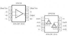
I have a 1984 FM tuner I want to replace the output amp based on the opa134.
I've attached the diagram taken from tuner info website (hope this is ok)
I can follow 95% of the diagram put sstruggling with the amp section.
i have orderd two opa134's for each of the left and right outputs so need to bulld two boards for this.
Can someone help with the audio ins and the outs...the diagram has some pins in brackets but no expaliantion.
Cheers
Paul
UK
First time poster so be gentle
I have a 1984 FM tuner I want to replace the output amp based on the opa134.
I've attached the diagram taken from tuner info website (hope this is ok)
I can follow 95% of the diagram put sstruggling with the amp section.
i have orderd two opa134's for each of the left and right outputs so need to bulld two boards for this.
Can someone help with the audio ins and the outs...the diagram has some pins in brackets but no expaliantion.
Cheers
Paul
UK
Attachments
Those pin numbers refer to the two separate opamps within the one package. The OPA2604 is a dual opamp, your OPA134 is a single opamp, so make sure you get all the connections correct.
For the OPA134 pins 2,3 and 4 are the same. The output is on pin 6 and the positive supply is pin 7. Leave pins 1,5 and 8 unconnected.
For the OPA134 pins 2,3 and 4 are the same. The output is on pin 6 and the positive supply is pin 7. Leave pins 1,5 and 8 unconnected.
Attachments
Will do Mate
My next challenge will be to find a feed for it all...12V....i have the circuit diagrame of the board but its a poor photocopy in PDF...may have to take it to a mate who's a tv repair man to find a source on the board....it maybe that its a 12v board so from the right side of the psu...but 230v hurts so will get my mate to find it
My next challenge will be to find a feed for it all...12V....i have the circuit diagrame of the board but its a poor photocopy in PDF...may have to take it to a mate who's a tv repair man to find a source on the board....it maybe that its a 12v board so from the right side of the psu...but 230v hurts so will get my mate to find it
- Status
- This old topic is closed. If you want to reopen this topic, contact a moderator using the "Report Post" button.
- Home
- Source & Line
- Analog Line Level
- OPA134