Hi there,
I want to swap some of the capacitors from my phono stage but I can't seem to find two of them with the same voltage rating. My question is, if I use capacitors but a higher voltage rating will it work fine?
Do capacitors need to work close to their voltage ratings in order to be efficient?
Thank you
For electrolytic capacitors... Match the capacitance (the farads) and use voltages that are higher (usually that is the case) than what is called for and you should be safe.
I have mixed small electrolytic capacitors without any visible or audible (but these are not in the audio path) issues. I would believe that the same would apply with polyester film capacitors of different voltage ratings.
What kind of caps are you replacing?
I have mixed small electrolytic capacitors without any visible or audible (but these are not in the audio path) issues. I would believe that the same would apply with polyester film capacitors of different voltage ratings.
What kind of caps are you replacing?
No way to isolate them that I'm aware of. If I'm not mistaken, their layout position is probably most critical here. Best thing is to put a o'scope to it if you have one. Even if you don't, I'd say give it a try and have a listen for new noise. They aren't that much bigger are they?
Try it. If you are careful you can always replace the original caps.
To stop big caps from picking up hum or other interference/feedback you need to screen/shield them. That means putting some grounded metal between them and the source of the problem. This can be difficult and messy with an existing PCB.
Why are you changing the caps anyway? What role do they play in the circuit?
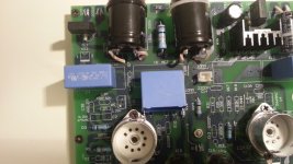
I'll try it and see if they fit. If not, I can customized the bottom cover of the phono stage.
The reason I want to change them is because althought is not a bad phono stage it lacks dinamics and sound transparency. I'm also lifting the heater voltage. The caps are placed at the output signal of the phono stage.
The reason I want to change them is because althought is not a bad phono stage it lacks dinamics and sound transparency. I'm also lifting the heater voltage. The caps are placed at the output signal of the phono stage.
Last edited:
1) I you want to reduce hum start by not using tubes. 
2)
To correct?:
Those 2 technologies are transparent enough, as in passing frequencies absolutely the same, depending just on their capacitance value .... which is the same.
There *might* be some difference at very high frequencies, way beyond audible range, depending on internal inductance, but you can't predict that prima facie based on dielectric technology alone, it's more dependent on the physical way they are wound and how terminals are connected.
In fact, you might be replacing the "good" with the "not so good" one.
Dynamics and sound transparency depend more on the project itself (and in layout, an often ignored aspect) that on replacing same value parts.
Can you post the preamp schematic?
Thanks.
2)
What for?I want to swap MKP capacitors 1uF/275V and put film & foil polypropylene 1uF/400V
To correct?:
Do you think it will change if you substitute a very good capacitor for another very good capacitor, exact same value, only larger physical size?lacks dinamics and sound transparency.
Those 2 technologies are transparent enough, as in passing frequencies absolutely the same, depending just on their capacitance value .... which is the same.
There *might* be some difference at very high frequencies, way beyond audible range, depending on internal inductance, but you can't predict that prima facie based on dielectric technology alone, it's more dependent on the physical way they are wound and how terminals are connected.
In fact, you might be replacing the "good" with the "not so good" one.
Dynamics and sound transparency depend more on the project itself (and in layout, an often ignored aspect) that on replacing same value parts.
Can you post the preamp schematic?
Thanks.
If they are output caps then they will probably come from a relatively low impedance so my comments about picking up hum etc. will not apply.
In a well-designed preamp the low frequency cutoff will be set by an earlier coupling cap so the output caps will not have much signal voltage across them. Therefore they can't affect the signal very much. That may be why the original designer specified fairly ordinary but good quality caps.
In a well-designed preamp the low frequency cutoff will be set by an earlier coupling cap so the output caps will not have much signal voltage across them. Therefore they can't affect the signal very much. That may be why the original designer specified fairly ordinary but good quality caps.
1) I you want to reduce hum start by not using tubes.
We where talking about the posibility of big caps catching hum, not that I'm suffering from it. All my hifi system (pre and power amps) is based on tubes and I don't have any hum whatsoever. Your assertion of not using tubes is a bit drastic
2)
...
Do you think it will change if you substitute a very good capacitor for another very good capacitor, exact same value, only larger physical size?...
This ones aren't good capaitors at all.
Can you post the preamp schematic?
Sure I can.
Thanks.
Attachments
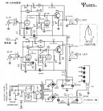
Oh dear!
- 12AX7/ECC83 with low anode loads, so distortion unless signal levels are low.
- The first stage looks straight into a huge Miller capacitance created by the second stage (presumably for reasons of loop stability) - you will get slew rate limiting if you want more than a couple of volts out, and some distortion below this level.
- Second stage uses grid current bias, which should really only be used for input stages where hum is a bigger problem than distortion (and 2M may be too small a resistance - 10M is more usual).
- The input stage cathode electrolytic is in the feedback network instead of in the amplifier, so any distortion created here will not be reduced by NFB.
- All three stages share a single supply rail decoupling electrolytic.
- The output emitter follower appears to have quite low current so little driving ability.
For LF distortion the critical capacitor is not the output cap you are considering changing but the 10nF coupling cap between the two valves.
Sorry to rain on your parade, but I am not surprised you want to improve the sound. I'm not sure how best to do this as the design has so many things wrong.
PS this ought to be in the analogue source forum, not line level - I'm sure a kind mod will move it for you
Last edited:
Thinks for posting
As I said before, the "project" is far more important than "the parts".
And here we have quite a few "project" poor choices.
1) start with a good one: DC on filaments. Cool, and one less thing to worry about.
Now to problems:
2) tubes are not the best choice fir magnetic pickups any more.
40 years ago there was nothing else, but now any SS design, discrete or IC, beats it easily.
3) grid leak biasing is a very poor choice.
To boot, it's not properly implemented.
For one, they don't stand strong signals, so if used they are the first stage .... here it's the second stage after 40 or 50X amplification. Crazy.
4) what are those Miller caps doing there?
No surprise you lack "air" and "detail".
5) you have caps there which *do* affect frequency response big way, the ones used in the RIAA compensation network: C5/6/13/14 .
*Those* should be the object of your attention.
There even a small capacitance change (still within tolerance) can cause important changes in the sound, that's their job.
Mind you, I'm talking about measured capacitance value, not brand or construction material.
6) C2 and C9 *are* within the loop, as noted, and affect LF response.
7)C7/C11 are also in the loop, but they are large value "all pass" types, they are not specifically chosen to change frequency response as tghose above mentioned.
Besides, the "better" they are the more *attenuated* will the HF response be, so it might work backwards of what you think.
Given the problems mentioned, I very much doubt changing some of the 1uF caps for same vaue, different (yet very similar type) dielectric can change sound in the direction you wish.
Sorry.
Not being as astute or as smart as the rest of the members here (I just build according to instructions), it does sound like this Phono Pre-Amp isn't too spectacular or sparkling.
You might want to build this one here.
- DIY Phono Preamp : Recording Magazine -
Very, very, basic. Easy to build, in fact I built one because my friend requested I do one for him (I'm only starting to buy records now and I need a turntable, so this isn't high priority). He said it sounds pretty good.
Build this, use it, and in the mean time rebuild from a kit or PCB with the parts from this pre... Just a suggestion.
Thing is I got this pre-phonoamp very cheap. There's a guy. called Les, he really knows what he is doing and has design a rebuild for this phono stage (attached), I'm following his steps from the document he has written. Although I must say that for the money that cost this phono stage (159$) sounds suppert (play&go).
As I said, this is a cheap chinese valve phono stage that can sound amazing if you do the proper modifications.
Thank you to everyone who has give a feedback.
What do you guys thinkg about the modification?
As I said, this is a cheap chinese valve phono stage that can sound amazing if you do the proper modifications.
Thank you to everyone who has give a feedback.
What do you guys thinkg about the modification?
- Status
- This old topic is closed. If you want to reopen this topic, contact a moderator using the "Report Post" button.
- Home
- Source & Line
- Analog Line Level
- Capacitors voltage rating