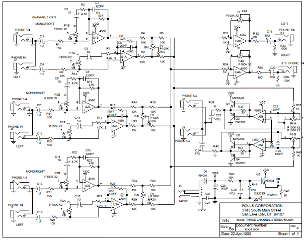
Here's what I'm working with
3 Stereo Input Channels
1 Stereo Master Output
1 Stereo Headphone Output
Originally, all 3 channels are wired to a bus that feeds Main Output circuit and Headphone Output circuit simultaneously.
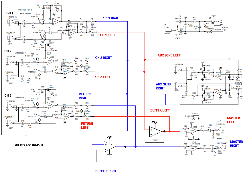
I want to modify the circuit so Channel #3 feeds Master Output but NOT Headphone Output.
I'm trying a configuration with switches but in the end, Channel #3 signal reaches Headphone Output through Master Output bus->Channel #1 path->Headphone Output.
I'm trying to be as clear as possible. I have a schematic but it's a pdf.
Yes, that's what I'm trying to do. Are you suggesting I make a mix of 1 and 2 through a buffer and feed the buffer output to Master input where I add channel #3 ? Would that block signal from channel #3 to reach channel 1 and 2 path (to headphones)?
If that makes any sense...
If that makes any sense...
I know this is ultra basic stuff but I haven't use op amps in awhile and I must make sure I get it right.
I will use the same 4560 as the original design. The only thing I'm not sure is should I use an input resistor (like figure B) and which value to keep everything flowing properly?
FYI, the buffer will be connected between Channels ouput (Ch.1 = R5 for Right and R10 for Left) and Master input (R40 for Right and R37 for Left). See schematic I posted before.
An externally hosted image should be here but it was not working when we last tested it.
you dont need the extra buffers, the summing amps are all you need, you just have to rewire the inputs to the summing amps, omitting channel 3 from the head phone amp. Are you sure the section wth the discrete transistors is not the HP amp?
You're right. My schematic is wrong. The part with transistors is the HP amp (verified on PCB).
However I'm not sure I understand your first statement. You mean if I remove the connection from CH 3 to HP amp it will work? I thought the signal would reach it through the center bus (where Channel 1, 2, 3 connects with Master Out and HP Out on the same wire.) See original schematic.
bump!
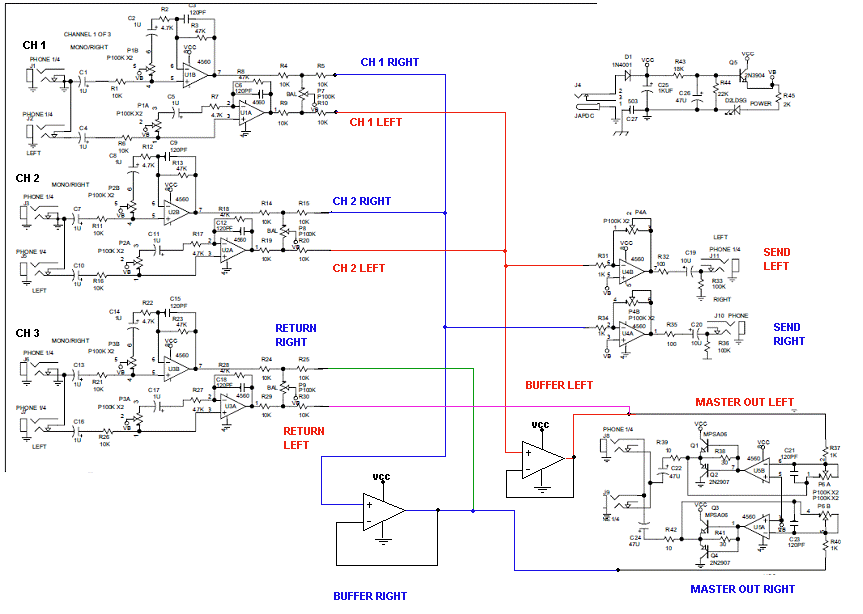
Here's the mod schematic with the right labels

So far, the buffer itself is working. I can mix both Ch. 1 and 2. I'm using a BA4560 and a 10k feedback resistor (best results).
What doesn't work:
- Simply wiring Ch. 3 to the buffer output doesn't work. I no longer read the buffer input signals (Ch 1 & 2).
- A 100k resistor (best results) from buffer output to ground is needed to get a clean signal into Master input.
- With everything wired, the Master output is clipping really bad.
Can anyone clarifying what cbdb is saying? How can I use the summing amps only?
Here's the mod schematic with the right labels

So far, the buffer itself is working. I can mix both Ch. 1 and 2. I'm using a BA4560 and a 10k feedback resistor (best results).
What doesn't work:
- Simply wiring Ch. 3 to the buffer output doesn't work. I no longer read the buffer input signals (Ch 1 & 2).
- A 100k resistor (best results) from buffer output to ground is needed to get a clean signal into Master input.
- With everything wired, the Master output is clipping really bad.
Can anyone clarifying what cbdb is saying? How can I use the summing amps only?
- Status
- This old topic is closed. If you want to reopen this topic, contact a moderator using the "Report Post" button.
- Home
- Source & Line
- Analog Line Level
- How can I split a mixer bus?

