An externally hosted image should be here but it was not working when we last tested it.
This filter was introduced in the early 1970s by Quad Ltd in their model 34 preamplifier. A single knob allows you to tilt frequency response around a pivot frequency (Fp), [FONT=Verdana,Tahoma,Arial,Helvetica,Sans-Serif][FONT=Verdana,Tahoma,Arial,Helvetica,Sans-serif]by simultaneously boosting the treble and cutting the bass frequencies or vice-versa. See Heawwize site:http://headwize.com/?page_id=741
Up to now the filter was tuned by means of PSpice simulations.
In my EDN article:
[/FONT][/FONT]
http://www.edn.com/article/520749-Implement_an_audio_frequency_tilt_equalizer_filter.ph
I derived the transfer function and the formulas to calculate the components value following the desired
Fp (pivot frequency), the Boost/ Attenuation at Low frequencies and High frequencies.
Next time I will give you some examples.
If somebody will a particular Tilt equalizer, I can calculate the components.
[FONT=Verdana,Tahoma,Arial,Helvetica,Sans-Serif][FONT=Verdana,Tahoma,Arial,Helvetica,Sans-serif]
[/FONT][/FONT]
Last edited:
That's a good idea! Let me "sleep" over that, I will reply soon! FBCan you add a second pot to vary the pivot frequency?
Thanks!
CHANGING Fp pivot-frequency. Dear SmartAlex,
If we see the parametric equations in my EDN publication there is a good news and a bad one.
Good: the pivot frequency Fp can be changed without changing ML and MH (asymptotic low/hi freq boost-attenuation)
Bad: you must change the couple of capacitors C (fig.1) to change Fp. With other 2 capacitors in parallel to C (with a switch) allows to have Fp = 440 Hz, 1kHz, 3kHz.
If you give me your specifications: ML, MH, Fp1, Fp2, Fp3 etc.. ,I will caculate the componentsfor you. FB
In the article, it shows a response that varies between about 100Hz and 10k Hz, but below 100Hz and above 10k Hz the response has flattened out. Can these limits be changed, and how? Is it possible to make the frequency region where the tilt is occurring wider?
This is very interesting! A tilt circuit would be very useful in investigating at what tilt a loudspeaker will sound "the best". This has been recently debated by Sigfried Linkwitz and others...
-Charlie
This is very interesting! A tilt circuit would be very useful in investigating at what tilt a loudspeaker will sound "the best". This has been recently debated by Sigfried Linkwitz and others...
-Charlie
In the article, it shows a response that varies between about 100Hz and 10k Hz, but below 100Hz and above 10k Hz the response has flattened out. Can these limits be changed, and how? Is it possible to make the frequency region where the tilt is occurring wider?
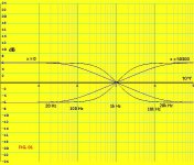
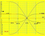
Is FIG. 01 what you ask for? Figure depicts the responses at wiper position x = 0 Ohm and x = 50 kOhm. The blue curves have a wider tilt zone (F-3dB shifts toward 20 Hz and 20 kHz). Unfortunately ( at my knowlege ) the only way to widening the tilt zone is to enhance ML and MH (the max asymptotic boost/attenuation at at low and hi freq. , that happens for the extreme wiper positions of P1, i.e. x=0 Ohm , x= 50k OHM). See FIG. 02. So it is possible but ML and MH are very high:24 dB. The boost/attenuation jumps from 6 dB to 24 dB.
6 dB: the signal is enhanced (atten.) 2 times;
24 dB: the signal is enhanced (atten.) 16 times!
FIG. 01 : the blue curves are artifacts; the black one have:
P1= 50 kOHM, fp= 1kHz, ML=2, MH=2, Rf=50 kOHM, R= (50/3) kOhm, 4.77nF.
FIG. 02 : blue curves: P1= 50 kOHM, fp= 1kHz, ML=16, MH=16, Rf=(10/3) kOhm, R=(10/51) kOhm, C=50 nF.
Comments? Bye Francesco
Attachments
A tilt circuit would be very useful in investigating at what tilt a loudspeaker will sound "the best". This has been recently debated by Sigfried Linkwitz and others...
-Charlie
Maybe Linkwitz refers to the lobe tilt. The interaction between tweeter and woofer in the cross-over zone can "tilt" the emission lobe ( up or down ). Can you help me?
bye Francesco
Hi Francesco,
Good work here! I would like to read the EDN article but the link is broke?
Ed
Right! the old link does,nt work anymore... here is the new:
Implement an audio-frequency tilt-equalizer filter | EDN
Thank you Francesco balena
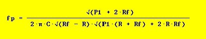
Friends ask me the set of formulas to "tune" the Tilt Equalizer Filter, because in my EDN article the editing is not clear.
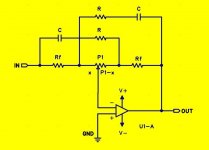
Use the ref circuit for the components names.
First you must choice the Potenziometer value P1 ( example: 50 kOhm).
Then you must decide the pivot frequency Fp (it's the frequency at wich there is no change, intersection of all the responces).
Then you must decide the Boost/Attenuation at low freq: ML and the Boost/Att at hi freq: MH.
ML and MH are NOT in dB, they are amplification factors (ex. ML= 2 ---> 6dB; MH=1.413---> 3dB and so one...).
Then you can use R, Rf, C formulas
Let me know if it's clear. Francesco
Use the ref circuit
for the components names.First you must choice the Potenziometer value P1 ( example: 50 kOhm).
Then you must decide the pivot frequency Fp (it's the frequency at wich there is no change, intersection of all the responces).
Then you must decide the Boost/Attenuation at low freq: ML and the Boost/Att at hi freq: MH.
ML and MH are NOT in dB, they are amplification factors (ex. ML= 2 ---> 6dB; MH=1.413---> 3dB and so one...).
Then you can use R, Rf, C formulas
Let me know if it's clear. Francesco
Attachments
Indicating withI don't need an adjustable tilt. Can you give a simple circuit that can achieve a fixed tilt that is different from the usual single pole and 2pole filters, eg. 3.5dB/oct, or 8dB/oct?
Let me sleep a litle bit on that
Can the attenuation above and below the tilt be specified?
ML the max boost/attenuation at low freq
and
MH the max boost/attenuation at hi freq
it's possible to have 3 situation (your choise):
ML=MH, ML>MH and ML < MH see attached FIGs


Notice that the pivot frequncy (tilt frequency) can be different (eg. 1kHz, 440Hz, 2kHz)
If the question is to have a Boost different from Attenuation (eg. MLboost= 5, MLatt.=3 ; MHboost=2, MHatt.=6) the answere is:
with the reference circuit
 it's not possible. If you introduce in the circuit R1, R2, Rf1, Rf2, C1, C2 (that is: no symmetric circuit) it's possible to have an asymmetric Boost/Attenuation.
I'm working about that. The parametrization is far more complicated. When I finish the job I pubblish that. Francesco
I have implemented an online calculator to configure a Tilt EQ where you can specify your desired parameters and obtain the component values needed to achieve it, or introduce your component values and obtain the filter pivot frequency, bass boost and treble boost with plotting of the frequency response for the pot's complete range.
Check it here, maybe someone find it useful:
Vulcano FX: Tilt EQ Calculator
Thank you Francesco for your formulas.
Check it here, maybe someone find it useful:
Vulcano FX: Tilt EQ Calculator
Thank you Francesco for your formulas.
" ... This filter was introduced in the early 1970s by Quad Ltd in their model 34 preamplifier. ..."
I have seen this incorrect assertion in another website (a review of a Pro Audio implementation).
Firstly, the Quad 34, which iintroduced a form of this type of filter (called "Tilt" on control panels) in QUAD equipment was not introduced until the early 1980's. During the 1970's the only QUAD preamp available was the 33 (1967~1982) which had conventional rotary pot tone controls for bass and treble.
Secondly, there was implementations of the Tilt Control in the mid-to-late 1970's, but from Japan. Luxman used the circuit in many preamps, both Vacuum State and Solid State, and the (SS) Lab Reference Series 5L15 Integrated Amp (called the "Linear Equalizer" on Lux control panels).
In both cases the control operated in discreet steps via a switch. Luxman's implementations was much finer, and offered a maximum adjustment of (typically) +/-2dB from centre frequency (total +/-4dB low to high in +/- 0.5dB steps) to correct for things like room response and loudspeaker or phono cartridge tendencies, while the QUAD 34 implemented it with a larger range of adjustment but much coarser steps (+/- 3dB from centre; +/- 6dB total, in +/- 1 dB steps).
The EDN article describes yet another implementation, operating like a conventional pair of potentiometer tone controls but with just a single pot.
Last edited:
Further to above, in some Lux mid-level equipment the Linear Equalizer modified the phono RIAA curve and thus was not available for line level inputs, while in the high end of the line it operated with all inputs. So in that respect there were two distinct, incompatible implementations at different parts of the preamp circuit. The QUAD 34's TILT control operated on all inputs.
Last edited:
I thank You Mr Johnny2Bad
for the QUAD34 corrections. My reference for the QUAD was:
Moy, Chu, “Designing a Pocket Equalizer for HeadphoneListening,” 1. HeadWize, 2002.
But it seems that this site don't exist anymore. The same article is here:
https://consort3.files.wordpress.com/2016/06/headwize-project-designi.pdf
By the way , my original design ideas article is now here:
https://consort3.files.wordpress.com/2016/06/headwize-project-designi.pdf
Soon I will publish the tranfer funtion of the asymmetric Tilt-Filter ( components can be any), a litle bit more complicated..FB
Sorry my original article is here:
https://www.edn.com/design/analog/4368935/Implement-an-audio-frequency-tilt-equalizer-filter
https://www.edn.com/design/analog/4368935/Implement-an-audio-frequency-tilt-equalizer-filter
- Status
- This old topic is closed. If you want to reopen this topic, contact a moderator using the "Report Post" button.
- Home
- Source & Line
- Analog Line Level
- Tilt Equalizer Filter