Hello,
I want to use some mono-blocks with my AVR32 Tag preamp/processor. The mono blocks require a symmetrical or balanced line input signals. Unfortunately my preamp has only normal unbalanced RCA outs.
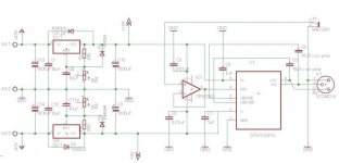
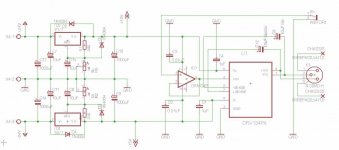
So i thought i would build a "from unbalanced to balanced" board using the TI's DRV134 and an OPA 134 Opamp as buffer / impeadance matcher. I guess the buffer isn't really required, since my preamp has a line out impeadance of 47 ohms but i thought the buffer would make the board a bit more flexable for other scenairos.
I know circuits like this have posted many times and basically its a mixture of those I've found. The main featuers are:
-on board regulation
-buffered input
Also adj. gain would be possible here but i left it out, since the drv has some 6db gain and its prob. not necessary.
Pls. see my circuit and let me know if what u-all think. Thanx!
I want to use some mono-blocks with my AVR32 Tag preamp/processor. The mono blocks require a symmetrical or balanced line input signals. Unfortunately my preamp has only normal unbalanced RCA outs.
So i thought i would build a "from unbalanced to balanced" board using the TI's DRV134 and an OPA 134 Opamp as buffer / impeadance matcher. I guess the buffer isn't really required, since my preamp has a line out impeadance of 47 ohms but i thought the buffer would make the board a bit more flexable for other scenairos.
I know circuits like this have posted many times and basically its a mixture of those I've found. The main featuers are:
-on board regulation
-buffered input
Also adj. gain would be possible here but i left it out, since the drv has some 6db gain and its prob. not necessary.
Pls. see my circuit and let me know if what u-all think. Thanx!
Attachments
You might want to leave space for a bigger cap where you put the DRV 1uF rail decouplers, on occasion I've had to go up to 22uF to stop ringing on the outputs.
Thanx for the tip pinkmouse!
I'll be sure to leave extra space on the board layout for that!
Did u use electrolytics for the 22uF's?
22 as a bypass is alot of capacitance!
Cheers,
Chris
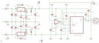
Pin1 does NOT connect to Audio Ground.
I suggest you add in a gain adjust giving options (switching) for +0dB and -6dB.
Otherwise attenuation of the balanced signal introduces many practical difficulties.
Attenuation of the unbalanced signal is very easy.
Thanx AndrewT,
i made a correction, is that what u meant or did i get it wrong again?
I'll update my schematic for the gain and repost the schematic again.
Cheers,
Chris
Attachments
On the "X1" connector, neither the pin 1 nor the shell should be connected to the circuit "GND" they should only be connected to the chassis with very short wires. Of course the circuit "GND" should also be connected to the chassis but with only one wire.
Added thoughts
The "WBTOR1" connector should be the circuit connection to the chassis. It's "S" terminal should go to circuit "GND" not to X1. pin 1.
Don't know how I skipped by AndrewT's post! I never saw it on my first read.
Added thoughts
The "WBTOR1" connector should be the circuit connection to the chassis. It's "S" terminal should go to circuit "GND" not to X1. pin 1.
Don't know how I skipped by AndrewT's post! I never saw it on my first read.
Last edited:
Thanx AndrewT,
I will read up on it.
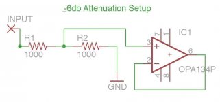
I posted a little schematic illustrating the 6db attenuation.
Maybe lower resistor values would be less noise prone, e.g. r2/r1 with 500/1k?
Not quite sure about r2, since the data sheet shows all gain examples with 1k.
It also mentions something about taking precautions on the non-inverted pin's impedance if their "parallel" resistance > 2k. Not exactly sure what is meant by parallel, e.g. just add both values?
Cheers,
Chris
I will read up on it.
I posted a little schematic illustrating the 6db attenuation.
Maybe lower resistor values would be less noise prone, e.g. r2/r1 with 500/1k?
Not quite sure about r2, since the data sheet shows all gain examples with 1k.
It also mentions something about taking precautions on the non-inverted pin's impedance if their "parallel" resistance > 2k. Not exactly sure what is meant by parallel, e.g. just add both values?
Cheers,
Chris
Attachments
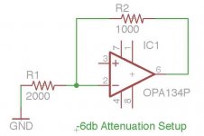
If you just want to cut the level by 50% and the attenuator has to be non inverting then you need the attenuator resistors at the + input of the opamp with the opamp configured as a buffer. You cant get "less than a gain of +1" from an opamp by feedback alone. You can if its configured as "inverting" but I'm guessing you don't want that.
On the "X1" connector, neither the pin 1 nor the shell should be connected to the circuit "GND" they should only be connected to the chassis with very short wires. Of course the circuit "GND" should also be connected to the chassis but with only one wire.
Added thoughts
The "WBTOR1" connector should be the circuit connection to the chassis. It's "S" terminal should go to circuit "GND" not to X1. pin 1.
Don't know how I skipped by AndrewT's post! I never saw it on my first read.
Hi Speedskater,
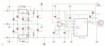
thanx for your help. Just made the changes.....
Cheers,
Chris
Attachments
If you just want to cut the level by 50% and the attenuator has to be non inverting then you need the attenuator resistors at the + input of the opamp with the opamp configured as a buffer. You cant get "less than a gain of +1" from an opamp by feedback alone. You can if its configured as "inverting" but I'm guessing you don't want that.
Hello, yes you are right this was my intention. I just wanted to cut the input signal in half.
Btw. do u by chance know what the lower gain limit is for an opa 134, i didn't see anything in the data sheet?
Thanx again,
Chris
") That's as low as any opamp would be specified. As mentioned, you can't have a gain of less than 1.
That's as low as any opamp would be specified. As mentioned, you can't have a gain of less than 1.The OPA134 being FET input has no issues with input bias currents and DC offset (as I see you mentioned something about "equal resistances" earlier). You need to be aware that you might need to AC couple the input to the attenuator. The two resistors alone would allow DC from any source component to pass through.
The OPA134 being FET input has no issues with input bias currents and DC offset (as I see you mentioned something about "equal resistances" earlier). You need to be aware that you might need to AC couple the input to the attenuator. The two resistors alone would allow DC from any source component to pass through.
Hi Mooly, so to cut the input signal in half, i would basically use a voltage divider on the input. What would be good values here for line level type signals? I read somewhere that they aren't fully standardized, e.g. 0.7 rms or 0.3...
See schematic.
Why do the resistors change anything, If my input signal had dc to begin with?
What upper bound freq. would usually be considered dc in such an analog circuit?
Thank you very much,
Chris
Attachments
That's it
The resistor values are always a compromise. The lower in value and the "better" that is for noise contribution, however that effect is tiny at the values we are talking. Make them to high and any stray circuit capacitance and the input capacitance of the chip starts to become a factor. The effect is that the capacitance starts to form a low pass filter and so the high frequency performance is affected. Also, lower values place more of a load on the source. So we compromise and here 10K should be ideal.
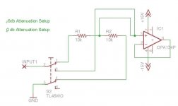
If your input signal had DC present then this would be attenuated exactly the same as the AC. Normally DC is considered a bad thing in ausio signal processing (and it never appears in music). If you applied a music signal that did have a DC offset to a speaker then the speaker cone would displace depending on the level of DC. So normally we don't want it. If you can be 100% certain that any source you connect will have no DC then you can just use the resistors. Good practice would AC couple to avoid any possibility of problems. The cap size is chosen according to the lowest frequencies to be passed. Two 10k resistors give a 20k input impedance (the opamp loading is negligable) so we could say that 5Hz would be our lower (-3db) limit and that would mean a cap of 1.6uf. In practice you could use a 2.2uf electroylitic or a couple of 1uf films in parallel.
The resistor values are always a compromise. The lower in value and the "better" that is for noise contribution, however that effect is tiny at the values we are talking. Make them to high and any stray circuit capacitance and the input capacitance of the chip starts to become a factor. The effect is that the capacitance starts to form a low pass filter and so the high frequency performance is affected. Also, lower values place more of a load on the source. So we compromise and here 10K should be ideal.
If your input signal had DC present then this would be attenuated exactly the same as the AC. Normally DC is considered a bad thing in ausio signal processing (and it never appears in music). If you applied a music signal that did have a DC offset to a speaker then the speaker cone would displace depending on the level of DC. So normally we don't want it. If you can be 100% certain that any source you connect will have no DC then you can just use the resistors. Good practice would AC couple to avoid any possibility of problems. The cap size is chosen according to the lowest frequencies to be passed. Two 10k resistors give a 20k input impedance (the opamp loading is negligable) so we could say that 5Hz would be our lower (-3db) limit and that would mean a cap of 1.6uf. In practice you could use a 2.2uf electroylitic or a couple of 1uf films in parallel.
Thanx alot for your efforts mooly, you are most generous to spend
your time looking at my stuff!
I will add some audio cap maybe a 2,2uF Mundorf Polypropylen. This
would make a corner freq. of approx. 3.62 Hz.
I will eventually update the schematic with all these insights and repost it.
Cheers,
Chris
your time looking at my stuff!
I will add some audio cap maybe a 2,2uF Mundorf Polypropylen. This
would make a corner freq. of approx. 3.62 Hz.
I will eventually update the schematic with all these insights and repost it.
Cheers,
Chris
-6db / 0db gain selection circuit
Hi everyone,
here's how i plan to switch the gain on my line driver circuit. Seems pretty
reasonable to me.
I thought about adding an additional +6db gain too but its bit tricky for me to devise a simple circuit with only one 3 pos. switch to do it. I guess an analog switch good be used or some kind of programmable set of three switches but that all adds a bit more complexity to my orig. circuit and i will prob. never need it.
Attachments
- Status
- This old topic is closed. If you want to reopen this topic, contact a moderator using the "Report Post" button.
- Home
- Source & Line
- Analog Line Level
- Balanced Line Driver with DRV134