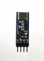
Here a larger picture of the first prototype.
This does not have the most up-to-date pin out.
There is already a new revision of the PCB which includes the protection diodes.
")
Many thanks to Walt Jung for his many constructive comments.
Patrick
This does not have the most up-to-date pin out.
There is already a new revision of the PCB which includes the protection diodes.
Many thanks to Walt Jung for his many constructive comments.
Patrick
Attachments
My measurement expert in the US has been submerged in work that he has not enough time to sleep.
I simply cannot justify asking him to give priority to hobby.
If you have the right equipment and are willing to take over, I am happy to ask him to send it to you.
Just send me a PM.
Terribly sorry for our sloppiness.
Cheers,
Patrick
I simply cannot justify asking him to give priority to hobby.
If you have the right equipment and are willing to take over, I am happy to ask him to send it to you.
Just send me a PM.
Terribly sorry for our sloppiness.
Cheers,
Patrick
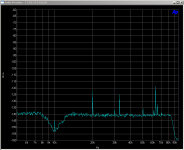
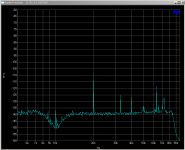
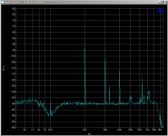
Finally, a very kind member of the forum has offered to measure the buffer for us.
So I built him a new one.
As the transistors I got from Mouser do not have overlap in hfe between PNP & NPN, they were not matched P to N.
The PNPs have hfe of around 300, the NPNs around 270.
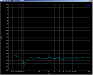
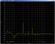
The results is shown here.
1Vrms 1kHz 100kOhm load -0.013dB of gain
1Vrms 1kHz 600 Ohm load -0.125dB of gain
1Vrms 1kHz 300 Ohm load -0.233dB of gain
So output impedance is about 8 ohm.
2nd harmonics (100k load) -110dB, 4th at -125dB.
These can be improved if hfe between NPN & PNP are better matched.
The buffer was never intended for driving 600ohm, but we tested it out of curiosity.
If you need to drive low ohmic load, then a more robust outstage as published by Walt should be used.
No added noise can be seen when lightly loaded (as was the intended application), to the limit of the AP2 analyzer used for the measurements.
Many many thanks for the measurements,
Patrick
So I built him a new one.
As the transistors I got from Mouser do not have overlap in hfe between PNP & NPN, they were not matched P to N.
The PNPs have hfe of around 300, the NPNs around 270.
The results is shown here.
1Vrms 1kHz 100kOhm load -0.013dB of gain
1Vrms 1kHz 600 Ohm load -0.125dB of gain
1Vrms 1kHz 300 Ohm load -0.233dB of gain
So output impedance is about 8 ohm.
2nd harmonics (100k load) -110dB, 4th at -125dB.
These can be improved if hfe between NPN & PNP are better matched.
The buffer was never intended for driving 600ohm, but we tested it out of curiosity.
If you need to drive low ohmic load, then a more robust outstage as published by Walt should be used.
No added noise can be seen when lightly loaded (as was the intended application), to the limit of the AP2 analyzer used for the measurements.
Many many thanks for the measurements,
Patrick
Attachments
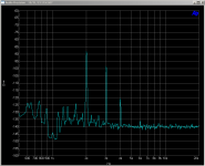
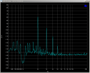
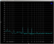
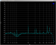
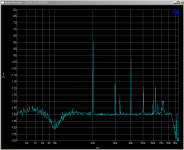
Then the same test for 10kHz.
From left to right :
Measurement noise floor
10kHz 1Vrms 100k load
10kHz 1Vrms 12.8k load
10kHz 1Vrms 600R load
10kHz 1Vrms 300R load
According to Dimitri, the garbage at 32kHz, 64kHz, etc. comes from computer and not the buffer.
Patrick
From left to right :
Measurement noise floor
10kHz 1Vrms 100k load
10kHz 1Vrms 12.8k load
10kHz 1Vrms 600R load
10kHz 1Vrms 300R load
According to Dimitri, the garbage at 32kHz, 64kHz, etc. comes from computer and not the buffer.
Patrick
Attachments
- Status
- This old topic is closed. If you want to reopen this topic, contact a moderator using the "Report Post" button.
- Home
- Source & Line
- Analog Line Level
- SMD High-Voltage Discrete Diamond Buffer