If I'm understanding this correctly, this would reduce the voltage to the amplifier to 6V? Is there some sort of buffer circuit I could make to allow the same power supply to run both the preamp and the amp?
Edit:
In reading your post again, I think I misunderstood you. Your saying to remove the audio grounds from the virtual ground and put them to the 0V ground. Wouldn't this remove the virtual ground from the circuit and remove the -6V supply for the negative swing of the opamp?
Edit:
In reading your post again, I think I misunderstood you. Your saying to remove the audio grounds from the virtual ground and put them to the 0V ground. Wouldn't this remove the virtual ground from the circuit and remove the -6V supply for the negative swing of the opamp?
Last edited:
The point of dividing the voltage is to bias the opamp correctly.
In a true split supply we would use the centre 0 V line. And the rails would be 6 volts above and 6 volts below that line.
In a single supply we have to bias the opamp in just the same way. If you think about it, the DC voltages are just the same as a split supply. It all depends on where you measure from") Ground, zero, plus etc. They are all just arbitrary points.
Ground, zero, plus etc. They are all just arbitrary points.
In a true split supply we would use the centre 0 V line. And the rails would be 6 volts above and 6 volts below that line.
In a single supply we have to bias the opamp in just the same way. If you think about it, the DC voltages are just the same as a split supply. It all depends on where you measure from
Ground, zero, plus etc. They are all just arbitrary points.That makes sense, but it seems contrary to moving the ground to 0v. Here's what's in my head:
Voltage divider gives us +6, 0, and -6. By grounding to the 0 it allows the opamp to swing both directions because the 'center' is at 0. If we move the ground to -6, we have affectively ignored the 0 and now have +12 and 0, which is what I had before the voltage divider. The opamp would now have no - to swing to and the sound would end up distorted as before.
Is this correct?
There is something I overlooked actually... but lets work through it
Not exactly. This depends where you measure from. If we measure from this divider (and we calling it "ground") then we can measure plus 6 volts above this and minus 6 volts below. The opamp output can swing equally above and below this "ground".
It also means the opamp outputs are at this same voltage. That means that they measure zero volts DC (relative to this point) but the reality is that they are 6 volts above the negative rail.
Because you want to run this off the same PSU and connect the grounds together we have a problem. The problem is that the "ground" of the preamp is the "virtual ground" point, and that is actually at 6 volts dc above the power supply zero line.
So you move the input grounds to the power supply zero.
We do the same for the output grounds.
We now call this new point "ground". All our voltages are now measured from here, and so what was the virtual ground point before, is now a point that sits at 6 volts. This biases the opamp outputs to 6 volts and allows them to swing equally above and below this point.
The thing I forgot is that you must now AC couple the output of the last opamp to block this 6 volts DC. Use a cap of around 10uf (depends on the input impedance of the power amp). Tha cap across the divider also needs to be around say 47uf.
Voltage divider gives us +6, 0, and -6.
Not exactly. This depends where you measure from. If we measure from this divider (and we calling it "ground") then we can measure plus 6 volts above this and minus 6 volts below. The opamp output can swing equally above and below this "ground".
It also means the opamp outputs are at this same voltage. That means that they measure zero volts DC (relative to this point) but the reality is that they are 6 volts above the negative rail.
Because you want to run this off the same PSU and connect the grounds together we have a problem. The problem is that the "ground" of the preamp is the "virtual ground" point, and that is actually at 6 volts dc above the power supply zero line.
So you move the input grounds to the power supply zero.
We do the same for the output grounds.
We now call this new point "ground". All our voltages are now measured from here, and so what was the virtual ground point before, is now a point that sits at 6 volts. This biases the opamp outputs to 6 volts and allows them to swing equally above and below this point.
The thing I forgot is that you must now AC couple the output of the last opamp to block this 6 volts DC. Use a cap of around 10uf (depends on the input impedance of the power amp). Tha cap across the divider also needs to be around say 47uf.
Ok, solved one problem, now on to the next... =)
The audio portion works great now. The circuit listed in this thread works find and supplies only the bass to my subwoofer amp, the issue I am running into now is a constant static noise that is present even with the opamp removed. By static I mean sort of a white noise like an analog tv tuned to a channel that isn't there.
Any ideas? This noise wasn't present when it was connected only to headphones.
This project has been such an awesome learning experience. I really appreciate the help and knowledge.
If it does this noise even with the opamp removed then I would be looking at the power amp it feeds.
Perhaps the power amp is unstable with the connection arrangement/leads you have.
Hard to say without seeing it.
Try applying a short to ground at the opamp output (on the outout side of the cap we talked about) and see if the noise is still there.
Perhaps the power amp is unstable with the connection arrangement/leads you have.
Hard to say without seeing it.
Try applying a short to ground at the opamp output (on the outout side of the cap we talked about) and see if the noise is still there.
Shorting it completely removes the sound, would applying a 1M resistor instead of a full short fix this? Or is this a bigger problem...
Edit:
Went ahead and tried that, didn't help at all...
Another edit:
Not sure if I did this right, but incase this is part of the problem, I put a cap between the opamp output and the amplifier on both the + output and the ground.
Edit:
Went ahead and tried that, didn't help at all...
Another edit:
Not sure if I did this right, but incase this is part of the problem, I put a cap between the opamp output and the amplifier on both the + output and the ground.
Last edited:
Well the opamp will drive loads down to around 600 ohms so just for interest you could try some lower value resistors instead of 1 meg.
But... whether that works or not, its not the answer.
You mustn't put a cap between the opamp output and the rails or ground. The only cap on the output is the one in series with the output.
If it makes the noise with the op amp removed as you mentioned, then there is nothing connected to the input of the power amplifier, it's just open and floating.
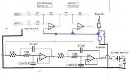
It should all look like this
But... whether that works or not, its not the answer.
You mustn't put a cap between the opamp output and the rails or ground. The only cap on the output is the one in series with the output.
If it makes the noise with the op amp removed as you mentioned, then there is nothing connected to the input of the power amplifier, it's just open and floating.
It should all look like this
Attachments
Ok, after looking at the diagram for entirely too long, I think I found an issue in what I actually built. I have everything in the circuit grounded to +6 instead of how you have it with the first half grounded to +6 and the second half to 0. I'll also add that 22k resistor in.
I also have a second opamp circuit built, it's a non-inverting unity gain in series with a sallen-key high pass filter. There is one of these for each channel (stereo) on a quad opamp chip. Do I set up the grounds in the same way (ground to +6 on the unity gain and 0 on the sallen-key)?
I also have a second opamp circuit built, it's a non-inverting unity gain in series with a sallen-key high pass filter. There is one of these for each channel (stereo) on a quad opamp chip. Do I set up the grounds in the same way (ground to +6 on the unity gain and 0 on the sallen-key)?
Lets just try and clarify all this because I'm saying things without making it all as clear as it could be.
It really doesn't matter whether the 0.047uf's go to the 0 volt line or the +6volt point however if they go to the +6 connection then it is important that the blue unmarked cap is fitted and this needs to be around 22uf or bigger. That cap makes the +6 volt line appear the same AC potential as the true zero line. The cap appears as a short at all audio frequencies. If you make it to big in relation to the two equal value resistors of the divider then the preamp will take a longer time to "settle" at power on because the cap has to charge via the divider.
The 22K resistor on the output ties the cap to what is now our ground (its just good practice to include it). Without the resistor the output point if unconnected will assume some DC voltage via the "open" cap and this will cause loud bangs and pops when the preamp is connected.
Well, in that case the only thing my circuit is missing is the 100 and 22K resistors. If my amp has an input resistance of ~50k, do I still need the 100ohm resistor?
I should be able to try the 22K resistor out tonight. Crossing my fingers that it fixes it.
Thanks again for all the help!
I should be able to try the 22K resistor out tonight. Crossing my fingers that it fixes it.
Thanks again for all the help!
Your schematic is incomplete without power supply voltages.
I would disagree about driving headphones with an op-amp, it can be done to moderate levels if you have a resistor on the output of the op amp to stop over driving it.
I used an op amp on a disco to drive the headphones. I drove each side through its own op amp.
However if you want a decent level out then a head phone amp/IC is the way to go.
- Status
- This old topic is closed. If you want to reopen this topic, contact a moderator using the "Report Post" button.
- Home
- Source & Line
- Analog Line Level
- Can't seem to get OpAmps to work