Awesome!
Thank you so much Olaf!
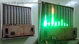
Here is my current progress of work.
Truly professional work! Very Inspiring! Kudos!ok, here are the missing photos.
regards
Thank you so much Olaf!
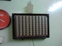
Here is my current progress of work.
Attachments
Hi Som,
looks really hot. What kind of power supply do you use? How high is the current when all LEDs are on?
regards Olaf
Thank you so much Olaf.
")
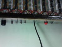
1. I used two separate transformers for the PSU section. Both are regulated.
a) The filter board PSU contains a 12 volt 1 Amp transformer with 4700uFd cap and a simple LM317 regulator. And I used TLO74 for the filter section here instead of the recommended LM324.
b) The main display board gets the power from a 12 volt PSU comprising of a 4 Amp transformer and another regulated power supply using LM317 and TIP3055. Here is the circuit and the PCB layout.
http://construyasuvideorockola.com/proyect_fuente_variable.php
I used two separate sections mainly because if, under any circumstances, the LED VU meter assembly boards draw slightly higher current, the filter characteristics of the board won't be hampered.
I tried to use SMPS for this circuit but for some reason that didn't give me a satisfactory result even if it has adequate filtration. So I went back to old Transformer method and that work impeccably. I have a plan to give SMPS oriented PSU a second try later on.
2. The power consumption of the original circuit, as per the author, was 7.6Amp.
But I was able to reduce the max current drawing of the board to a really great extent simply by increasing the LED driver resistors. It now consumes some 3 Amp approximately. I used high brightness LEDs. So the display is perfectly okay or rather I should decrease the brightness more.
LM324, as I have seen while testing the module, works nicely from 5+ volts. I applied a max of 15 volts and didn't see any improvements. Now I set the regulation at 12 volts. So you can start with some 7.5 volts too and that will reduce the power consumption further.
But kindly just make sure that the filter board gets a steady 12 volt regulated supply.
Here is another video of the actual or better performance with two separate PSUs:
Mini BoomBox with TA8210 and a spectrum analyser-A DIY Educational Hobby Project - YouTube
Last edited:
- Status
- This old topic is closed. If you want to reopen this topic, contact a moderator using the "Report Post" button.