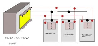
Better to use different one trafo for preamp and xover and another for power amp. Your suggested Idea will also work but connect the wires directly to trafo, means all wires from pcb directly connected to trafo instead of one pcb to another.I want to build the power supply like this attached picture.
Could you please tell me if this is possible or not?
thanks.
sudhir.
Better to use different one trafo for preamp and xover and another for power amp. Your suggested Idea will also work but connect the wires directly to trafo, means all wires from pcb directly connected to trafo instead of one pcb to another.
................./QUOTE]
Okay Sudhir,
I tried powering them all with a single Transformer but a Hum appeared in the sound.
So I changed everything and removed the power supply of the Original design of the X-over and getting Power from the Preamp power Supply. Things are working normally now for last 15 minutes or so and Hum is gone now.
Perhaps you have missed my earlier question.
Can I use Dual Potentiometers in lieu of those Variable Resistors and discard the volume control of the Power Amps since I already have a Volume control in the Preamp ?
Last edited:
Dear friends,
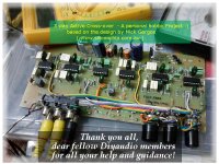
I am am very happy to inform all of you that the project has been successfully executed with all your always extending kind helping hands.
A big thank you to all of you. ( including dear Santa") )
)
Also my heartfelt thanks to Mr. Mick Gergos who painstakingly designed the corss-over and thoughtfully documented everything and kindly provided the much needed download files here Silicon Chip Online - Active 3-Way Crossover for Loud Speaker Systems .
Thank you really so much www.siliconchip.com.au for the support that you constantly provide to the hobbyists "to build for their own use".
Wish you all a very happy and prosperous New Year from the core of my heart !

I am am very happy to inform all of you that the project has been successfully executed with all your always extending kind helping hands.
A big thank you to all of you. ( including dear Santa
) Also my heartfelt thanks to Mr. Mick Gergos who painstakingly designed the corss-over and thoughtfully documented everything and kindly provided the much needed download files here Silicon Chip Online - Active 3-Way Crossover for Loud Speaker Systems .
Thank you really so much www.siliconchip.com.au for the support that you constantly provide to the hobbyists "to build for their own use".
Wish you all a very happy and prosperous New Year from the core of my heart !
no.I want to build the power supply like this attached picture.
Could you please tell me if this is possible or not?
You have connected the centre tap to all three PSUs.
This means you cannot later connect the audio grounds together without creating a ground loop.
BUT your linked PSU centre tap carries charging pulses. This is a contaminated ground.
Do not do it your way.
Thank you Andrew for your wise explanation.no.
You have connected the centre tap to all three PSUs.
This means you cannot later connect the audio grounds together without creating a ground loop.
BUT your linked PSU centre tap carries charging pulses. This is a contaminated ground.
Do not do it your way.
I have not implemented that after I found a lot of hum appeared due to the "contaminated ground" in that connection, as you have very aptly pointed out.
similar mistake in post67.
Multiple grounding creating loops.
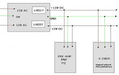
I am now using a common PSU for the Equalizer, Preamp and the X over and another for the Power Amplifier section which is now isolated and placed on a wooden board for the time being.
And interestingly, there is no hum or any kind of noise even after a continuous running of some 12 hours. I am just trusting my ears as I have no oscilloscope or other tools to identify the noise figure if any.
So I want to continue with this arrangement until A problem occurs.
But still I want to know what, according to you, is the ideal Power supply arrangement in this case? Do you recommend individual transformer for each section?
Thank you so much again for your valuable words.
Yet you left that post there for all to see and commented that you had completed your project.........................
I have not implemented that after I found a lot of hum appeared due to the "contaminated ground" in that connection, as you have very aptly pointed out. ...............
Do you expect that some Members read both posts and would copy what you posted?
Tell them what does NOT work is just as important as telling them what does work.
TELL THEM !!!!
Main Audio Ground (MAG).
ONE and only one MAG
Thank you Andrew.
Yet you left that post there for all to see and commented that you had completed your project.
Do you expect that some Members read both posts and would copy what you posted?
Tell them what does NOT work is just as important as telling them what does work.
TELL THEM !!!!
Andrew,
I definitely posted my working PSU connection at post #67 that worked nicely in my case.
I asked this question to all earlier ( at post #63) whether it was possible or not. And since sometimes realtime conversation don't take place here, it took me some time to get a reply from Sudhir (who was the first to reply). Sudhir suggested that using single transformer is not a good idea.
Meanwhile, before that, I, being impatient, gave it a try and found that as a bad solution and posted my working PSU arrangement at post #67.
So I posted what WORKED for me, I think at post#67.
And more, the circuit from that site contains a power supply onboard and as I said earlier, it is very well documented. So this personal question of mine is simply redundant to anyone unless one wants to bulild a single PSU for Eq, Preamp and X-over.
And regarding my leaving the post there, I cannot edit my posts after 30 mins or so I guess.
Yes, the project is finished and I have been listening to it and "loving it".
Sorry for any confusion that occured on your part.
Last but not the least, with due respect to your experience and wisdom, I would prefer a patient "Tell them!" instead of "TELL THEM!!!!"
Thanks.
Last edited:
I missed this.but a Hum appeared in the sound.
Sorry, you did tell them.
I missed this.
Sorry, you did tell them.
No problem Sir
))It happens to all of us
Anyway, thank you really for helpful suggestions and guidance, keep them coming, I need them
Please share you speakers / entire setup photo also.Still lot of works, lol!
Any DIY suggestion for the front plate ? Please feel free to suggest/guide me
sudhir
Okay Sudhir.Please share you speakers / entire setup photo also.
sudhir
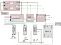
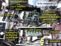
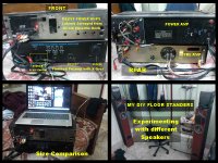
Though the amp setup is not aesthetically pleasing yet, but as per your request and with the excuse of my being a DIY noob, here are some photos.
I added 3 potentiometers, instead of the preset variable resistors, to the front panel of the preamp section in a separate cabinet. This is mainly because I have no audio oscillator and a good multimeter to check the signal level as suggested in the site. So I am doing it with constant trial and error method and trying to guess what is optimal for me. But I can say that now I have a way better control over the individual BASS, MID and TREBLE range.
Earlier I said that the Car Speakers are good in a near field listening environment. They offer very good clarity for sure but, to my utter surprise I've found that normal speakers are better in my enclosure as far as the creation of sound stage is concerned. I used two full range speakers for the mid-range from an old and obsolete music system. Please note that this is my purely subjective opinion after a lot of listening from DIY standpoint without having access to any measurement tools.
Thank you.
Attachments
- Status
- This old topic is closed. If you want to reopen this topic, contact a moderator using the "Report Post" button.
- Home
- Source & Line
- Analog Line Level
- DIY 3 way active crossover: as Christmas Holiday Project