My previous post is lost perhaps because of Internet problem.
So I am posting it again.
Thank you so much bibin.
Much appreciated.
I made 3 layers ( top, bottom, drill hole ref ) from the download of that site, and gave it to a man who makes PCBs. Probably he is going to charge me a fortune but since this Project is well tested by our respected fellow members like Pra, Sudhir and many others, I decided to take the risk.
I might get the PCB the day after tomorrow if everything goes well.
If not, I definitely will take resort to your kind concern.
Thanks a lot, really, Bibin,
You are welcome CSOM.
Sorry for replying late...I use my office laser printer for this purpose ..for home purpose you can use hp1007.I have 2 questions here.
1. Very soon I am planning to buy a laser printer that is low cost, low maintenance, and suitable for my DIY PCB making.
Which Laser Printer do you recommend ?
2. At present I use laser tracing paper but I heard many good things about magazine paper on the net. But I am confused which Magazine ( or type of paper ) to use as there are many types of magazines available in India as you are well aware of and they use different types of paper .
Could you name a magazine that can be used for this purpose?
Thank you.
2. Magazines paper with medium thickness (less than copier paper) and glossy finish (means entire page is covered with printed material/ink) are best for this purpose.i.e the week,India today etc.
thanks.
sudhir
HI,Another question
How did you get the component reference on top layer on the PCB that you made as the photo of the top layer is not identical in size with the PDF of the copper layer?
Did you use a paper print and stick it on top?
I used Gimp to adjust the top layer coordination with the copper side but couldn't be able to get the correct size at first.
I somehow managed that finally.
I dont print component reference on top layer on pcb...I place the component just by comparing with given photo.
thanks
sudhir
Here is my completed one using the same design:
Thanks,
Bibin
An externally hosted image should be here but it was not working when we last tested it.
Thanks,
Bibin
Thank you Sudhir and Bibin.
Your photos will definitely help me as a good reference.
I've finished the PCB just now with the help of a friend.
Bottom layer is okay.
The drill reference points I made are okay too.
But the top layer is blurry as expected
Your photos will definitely help me as a good reference.
I've finished the PCB just now with the help of a friend.
Bottom layer is okay.
The drill reference points I made are okay too.
But the top layer is blurry as expected
Attachments
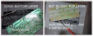
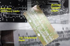
Here is the Photo of 3 layers of the PCB, an example in case anyone makes the board with silk screen printing.
1. Bottom copper layer: Provided by the Author in the download.
2. Top component Layer: Provided by the author in the download and given only as a reference by the author to DIY-ers.
I resized, edited and aligned to fit the size of the PCB in my personal hobby project.
3. Drill hole reference Layer: I made it following the original author's design as I wanted to give the PCB a professional look
This layer can safely be ignored as redundant.
Attachments
Great work, Bibin!!Here is my completed one using the same design:
http://imageshack.us/photo/my-images/526/img6959f.jpg/
Thanks,
Bibin
Great work, Bibin!!
Thank you Som. How much did they charged for making the PCB?
Have you completed populating the PCB with all the components? Which amps are you going to use with this?
thanks,
Bibin
Hi Bibin,
I faced a problem as I posted earlier. Here, as you know, no PCB makers are interested in printing a single pcb for a hobbyist like me. They are only interested in the bulk orders from companies and they are right from their stand point.
After a brief and cordial conversation with him, I was finally able to convince him to make this one during his leisure with no time limit or dead-line.
I just had requested him to use the best quality Copper Board available in India for this board. And he kept his promise.
But before that, during the experimentation with PCB size, I had to print several copies of the layers before the final ones ( at INR 20 per sheet )with trial and error method to get them right ( blame it on my GIMP skill). Since I have no Laser Printer at home, I printed them in a local cyber cafe and gave the man for screen printing.
So here is the total cost for this PCB which is quite high for a hobbyist like me from the Indian perspective.
Laser printing charge = 180 INR.
CD = 10 INR
PCB Maker = 250 INR.
___________________________
Total = 440 INR or some 7.98 USD approx I guess.
( and at this price, 2 completely assembled "made in China or Delhi" low wattage audio amplifier pcbs are available here in the local electronics shop, LOL )
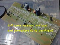
Anyways, I started populating the components and now, I found I have not enough stock of 1% metal film resistors and the 2.2nF box type caps. So the progress is slow for the time being. Perhaps it will take some two days more to obtain the remnant components.
I have one question. The vendor is charging me INR 1 per metal-film- resistor seeing my hobbyist-need. Do you think this is a fair price?
And according to you, what is expected price of the box caps ? ( I was charged @INR 4 to 7 per piece earlier depending on the value)
Here is the photo of the progress of my work so far.
I faced a problem as I posted earlier. Here, as you know, no PCB makers are interested in printing a single pcb for a hobbyist like me. They are only interested in the bulk orders from companies and they are right from their stand point.
After a brief and cordial conversation with him, I was finally able to convince him to make this one during his leisure with no time limit or dead-line.
I just had requested him to use the best quality Copper Board available in India for this board. And he kept his promise.
But before that, during the experimentation with PCB size, I had to print several copies of the layers before the final ones ( at INR 20 per sheet )with trial and error method to get them right ( blame it on my GIMP skill). Since I have no Laser Printer at home, I printed them in a local cyber cafe and gave the man for screen printing.
So here is the total cost for this PCB which is quite high for a hobbyist like me from the Indian perspective.
Laser printing charge = 180 INR.
CD = 10 INR
PCB Maker = 250 INR.
___________________________
Total = 440 INR or some 7.98 USD approx I guess.
( and at this price, 2 completely assembled "made in China or Delhi" low wattage audio amplifier pcbs are available here in the local electronics shop, LOL )
Anyways, I started populating the components and now, I found I have not enough stock of 1% metal film resistors and the 2.2nF box type caps. So the progress is slow for the time being. Perhaps it will take some two days more to obtain the remnant components.
I have one question. The vendor is charging me INR 1 per metal-film- resistor seeing my hobbyist-need. Do you think this is a fair price?
And according to you, what is expected price of the box caps ? ( I was charged @INR 4 to 7 per piece earlier depending on the value)
Here is the photo of the progress of my work so far.
Attachments
Last edited:
.........Which amps are you going to use with this?
thanks,
Bibin
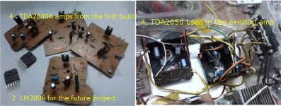
I have 4 TDA2030A amps that I made earlier. And 4 TDA2050 Amps are being used in the system. ( note to self: "never ever use TDA2030A amps. They ARE evil. You will simply fall in love with their sound quality and straightaway discard all your discrete high end commercial music systems that you earned with your hard earned money and then you will upgrade to TDA2050 in need of greater power".
). I bought 2 LM3886 ICs for the forthcoming project. ( Wow! Another audio fanatic has found home here in DIYAudio forum, it seems )So at present I will play with them after the completion of this xover. .
But as Mooly, our respected and experienced moderator, suggested, after I asked the identical question, I will do a comeplete switch over to 6 LM3886 based amps. But that will take some time due to the cost factor involved.
Attachments
Hi If anyone is interested in a small group buy, I have a source in NZ who is willing to make small runs of 10 boards.
Happy Christmass to you all
Tabarddn
Thank you for the information Tabarddn.
Merry Christmas.
Okay, update time.
I somehow managed to find some more 1% metal film Resistors in a shop.
What a job!
I also have had a great difficulty in finding the 20K value.
For the rest, I'm going to use commonly available 5% rated ones.
And the twin RCA PCB mounting sockets are simply unavailable despite my level best effort by searching every nook and corner. Two shop owners emphatically told me that it is an obsolete part and not in production anymore. May be they are right as the design is some 10 years old, I am not sure.
So I will use an integrated 6 set connector set that is commonly used in the rear side of the DVD player and that may require some serious modding of the PCB.
I am also planning to change the X-over frequencies. If the PCB can't survive my torture I will make a new one with the conventional toner transfer method.
I now have a fairly comprehensive idea of the circuit. I studied the circuitry of the ESP site too and I found that they are very identical in many ways as rightly pointed out by sudhir at post 10.
Thank you all, once again, for your constant, kind help and pointing me towards the right direction.
Some rigorous working time now
P.S. Meanwhile, all of you....., kindly don't hesitate to post your experienced thoughts, tweaks, suggestion or guidance, if any.
That is waste of money dear...better if you had tried first the diy lasetoner transfer method..by the way..the pcb maker charged you very rational price..for components please contact to some whole sellers .Hi Bibin,
I faced a problem as I posted earlier. Here, as you know, no PCB makers are interested in printing a single pcb for a hobbyist like me. They are only interested in the bulk orders from companies and they are right from their stand point.
After a brief and cordial conversation with him, I was finally able to convince him to make this one during his leisure with no time limit or dead-line.
I just had requested him to use the best quality Copper Board available in India for this board. And he kept his promise.
But before that, during the experimentation with PCB size, I had to print several copies of the layers before the final ones ( at INR 20 per sheet )with trial and error method to get them right ( blame it on my GIMP skill). Since I have no Laser Printer at home, I printed them in a local cyber cafe and gave the man for screen printing.
So here is the total cost for this PCB which is quite high for a hobbyist like me from the Indian perspective.
Laser printing charge = 180 INR.
CD = 10 INR
PCB Maker = 250 INR.
___________________________
Total = 440 INR or some 7.98 USD approx I guess.
( and at this price, 2 completely assembled "made in China or Delhi" low wattage audio amplifier pcbs are available here in the local electronics shop, LOL )
Anyways, I started populating the components and now, I found I have not enough stock of 1% metal film resistors and the 2.2nF box type caps. So the progress is slow for the time being. Perhaps it will take some two days more to obtain the remnant components.
I have one question. The vendor is charging me INR 1 per metal-film- resistor seeing my hobbyist-need. Do you think this is a fair price?
And according to you, what is expected price of the box caps ? ( I was charged @INR 4 to 7 per piece earlier depending on the value)
Here is the photo of the progress of my work so far.
thanks
sudhir
Very correct I love the quality of tda2030.I have 4 TDA2030A amps that I made earlier. And 4 TDA2050 Amps are being used in the system. ( note to self: "never ever use TDA2030A amps. They ARE evil. You will simply fall in love with their sound quality and straightaway discard all your discrete high end commercial music systems that you earned with your hard earned money and then you will upgrade to TDA2050 in need of greater power".
So at present I will play with them after the completion of this xover. .
But as Mooly, our respected and experienced moderator, suggested, after I asked the identical question, I will do a comeplete switch over to 6 LM3886 based amps. But that will take some time due to the cost factor involved.
For RCA you can search MX Connectors dealers/website. for 20k resister use 2 10k in series.Okay, update time.
I somehow managed to find some more 1% metal film Resistors in a shop.
What a job!
I also have had a great difficulty in finding the 20K value.
For the rest, I'm going to use commonly available 5% rated ones.
And the twin RCA PCB mounting sockets are simply unavailable despite my level best effort by searching every nook and corner. Two shop owners emphatically told me that it is an obsolete part and not in production anymore. May be they are right as the design is some 10 years old, I am not sure.
So I will use an integrated 6 set connector set that is commonly used in the rear side of the DVD player and that may require some serious modding of the PCB.
I am also planning to change the X-over frequencies. If the PCB can't survive my torture I will make a new one with the conventional toner transfer method.
I now have a fairly comprehensive idea of the circuit. I studied the circuitry of the ESP site too and I found that they are very identical in many ways as rightly pointed out by sudhir at post 10.
Thank you all, once again, for your constant, kind help and pointing me towards the right direction.
Some rigorous working time now
P.S. Meanwhile, all of you....., kindly don't hesitate to post your experienced thoughts, tweaks, suggestion or guidance, if any.
thanks
sudhir
That is waste of money dear...better if you had tried first the diy lasetoner transfer method..by the way..the pcb maker charged you very rational price..................................
Yes, you are right Sudhir. I mainly asked the help form the man so that I can obtain the top layer for component placement. But as you can see, the top layer is all blurry and illegible. As a result of this I had to follow the top layer picture as provided by the original author in the download section of that site, just like you did in your project. So, yes, a clear waste of money But that was a lesson.
I guess he used some wasted small copperboard so he charged a little less, seeing it a personal hobby project. But the pcb quality was very good, I mean better than that I use with the normal toner trasnfer method. That's the consolation.
For RCA you can search MX Connectors dealers/website. for 20k resister use 2 10k in series.
............
1. I did a modding of the PCB to use the 6 set RCA connector.
2. True. But luckily I found 20K ones. That saved me from additional solder joints
.
What is the cost of lm3886 and on which place ?
The vendor charged me a lot ( blame it on my drooling and laziness by not checking out the price in other shops)
I got all plastic TF versions for INR 425 per piece at chandni chawk.
Thank you Sudhir for your response.
Here is another question :
Can I replace those 6 variable resistors with Dual potentiometers and discard additional volume controls for the Amps?
Last edited:
- Status
- This old topic is closed. If you want to reopen this topic, contact a moderator using the "Report Post" button.
- Home
- Source & Line
- Analog Line Level
- DIY 3 way active crossover: as Christmas Holiday Project