Hi guys
I finally assembled the lighter note kit that I bought from uriah a couple of months ago. I have a problem with the setup Sind I'd rather not bother Uriah at the moment, I post here in the forum.
I'm stuck at step 15 of his manual where you're measuring the voltage between gnd and tne anode of the dioes and then dial in to 13V with the pots. I can dial in one channel, but the other stays at 1.24V. Could anyone give me a hint how I can track down the error?
I checked solder joints and couldn't find any bridges.
Thanks!
ElEsido
Attachments
I'll post a zoomed pic soon.
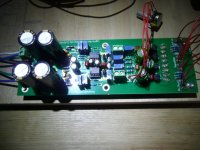
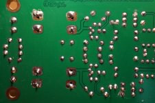
In the first pic on the left hand side at the bottom there are two large caps, immediately to their right (out of the shadow, below the orange drop shaped caps) is a diode which is the faulty measuring point. The same diode on the top of the pic/pcb works fine. Voltage is adjustable with the respective two potentiometers to the right of the diodes (closer to the diode=coarse setting, farther = fine).
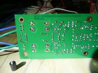
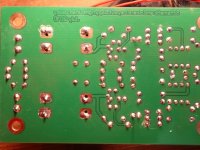
In pic 3 you see two wires that cast a shadow, these go into the LED. The soldering spots of the diodes is from there towards the edge of the PCB and slightly to tle left, the potentiometers are to the right. The faulty side is on top.
Can I measure the potentiometers without desoldering it, or doesn't this make sense?
In the first pic on the left hand side at the bottom there are two large caps, immediately to their right (out of the shadow, below the orange drop shaped caps) is a diode which is the faulty measuring point. The same diode on the top of the pic/pcb works fine. Voltage is adjustable with the respective two potentiometers to the right of the diodes (closer to the diode=coarse setting, farther = fine).
In pic 3 you see two wires that cast a shadow, these go into the LED. The soldering spots of the diodes is from there towards the edge of the PCB and slightly to tle left, the potentiometers are to the right. The faulty side is on top.
Can I measure the potentiometers without desoldering it, or doesn't this make sense?
Do the LEDs have similar volts drop (Vf)?
Power OFF.
set DMM to ohms.
Are two of the pot pins traced together? If yes then a variable resistor rather than voltage divider.
measure across the pot pins.
adjust and measure again.
If no, then you need to measure from middle pin (wiper) to outer pin (track).
Adjust and measure again.
Power OFF.
set DMM to ohms.
Are two of the pot pins traced together? If yes then a variable resistor rather than voltage divider.
measure across the pot pins.
adjust and measure again.
If no, then you need to measure from middle pin (wiper) to outer pin (track).
Adjust and measure again.
I've desoldered the pots of both channels and tested the one on the faulty side - the pot works. On the board in each place two of the holes are connected.
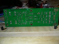
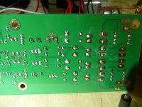
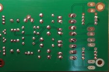
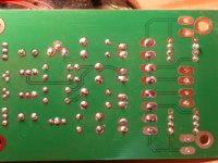
Attached are the best pics I could take from the solder side, taken with two different cameras. I can't find any shorts...
Attached are the best pics I could take from the solder side, taken with two different cameras. I can't find any shorts...
Attachments
I also assembled the kit. Everything seemed to be fine, voltages and shunt LDR's adjusted OK. When test signal was connected the attenuator also seemed to be working. When powered down one channel suddenly became very loud. I checked the cold resistance of all LDR's and one series LRD had cold resistance of ~20k, the rest of them beyond 20M. I checked the board, desoldered Lin and Lout - same result. Took out the LDR from the board and measured the resistance - over 1M, a little tap on the LDR and back to 20k...seems like some kind mechanical failure. The LED inside the coupler seems to be functioning fine...Could it be defective LDR?
It is my second LDR preamp, I have assembled an earlier version of Lightspeed and it's working very well.
It is my second LDR preamp, I have assembled an earlier version of Lightspeed and it's working very well.
No, no spares at the moment. I email Uriah and he's sending replacement pair.This sounds very much like a faulty LDR. Do you have any spares?
- Status
- This old topic is closed. If you want to reopen this topic, contact a moderator using the "Report Post" button.
- Home
- Source & Line
- Analog Line Level
- Please help me to debug the Lighter Note Attenuator