Hey there,
Let me first start by apologizing if this is the wrong place to post this,
I have very little knowledge on audio things.
I have been trying to learn how to use an arduino, microprocessors, circuits, etc. for a few months now. I am currently working on a project where I essentially need to filter out treble and leave the bass of audio going through headphones (so there is no amplifier involved.)
I need the filter to filter OUT the audio and leave the bass, not make all of the audio have a lower frequency. Im sure you guys know what I mean.
Does anyone know of a simple easy to follow circuit to do this?
I appreciate the help!
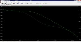
To filter the treble out of the audio feed to headphones as you mention could probably be done with a simple R and C filter as long as there is enough voltage drive available. Very unusual way of doing it mind you but it should work.
Is this what you mean")
Or do you mean a digital filter ?
Is this what you mean
Or do you mean a digital filter ?
Do you know how to arrange it ?
Its basically a series resistor to the phones, one for left and one for right channels. The caps just connect from the phones end of the resistor to ground (in other words across each driver).
No real idea on values (because its an unusual method applying it on a "speaker") but I would start with say 100 ohms and some small caps of say 1uf ? (as a guess).
- Status
- This old topic is closed. If you want to reopen this topic, contact a moderator using the "Report Post" button.
- Home
- Source & Line
- Analog Line Level
- Filter Bass and treble to the input of a microprocessor