Very nice thread
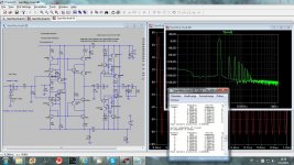
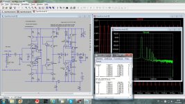
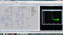
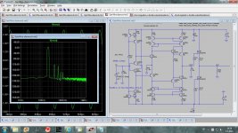
What's the gain and can you post FFT with 1VAC input, at 20khz?
The gain was set to 7.8(18dB), but here is with the gain set to 3.7 too.
dado
Attachments
Looks good, dado.
Did you measure the DC offset? How do you control it?
As this is not GNFB circuit the DC offset is not zero(or very close) but in my case about 60 - 70mV. I have a trimpots but I used it to set equal source currents(suppose it will set lowest distortion). For me that DC offset is not a problem as my poweramp has input capacitors, but just in case I have other delayed output via capacitors(6.8uF).
Solution for the DC offset could be a servo, but I did not bother.
dado
As this is not GNFB circuit the DC offset is not zero(or very close) but in my case about 60 - 70mV. I have a trimpots but I used it to set equal source currents(suppose it will set lowest distortion).
I'm pursuing a 0GFB design without servo. For headpnones safety the DC should be less than 5mV, but I believe that a good design and a few accurate trimpots in key points (i.e. not only at the input) should be enough
")
Time will tell
I'm pursuing a 0GFB design without servo. For headpnones safety the DC should be less than 5mV, but I believe that a good design and a few accurate trimpots in key points (i.e. not only at the input) should be enough
Time will tell
I use bipolar electolytic capacitors of 100uF to connect 300ohm hedphones.
GainWire-mk2
Here is simpler variant of the current conveyor line amp. It uses only two types of semiconductors, all BJTs are BC550/560 and mosfets are DN2540.
Volume control is after the gain stage(P1) and it has advatage to maintain constant signal/noise ratio over whole volume regulation. It could use similar shunt regulator as GaiWire but with lower voltage and power dissipation.
Damir
Attachments
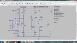

What can you guys do with this? SIM it and add what is needed for output stage etc.
It uses cancellation technique to reduce distortion. [I'm into cancellation circuits now]
Then bend it into push-pull input etc.... .
Thx-RNMarsh
View attachment 364749
Thanks Richard, it looks interesting I will try to simulate(input) to see what is behind it.
BR Damir
What can you guys do with this? SIM it and add what is needed for output stage etc.
It uses cancellation technique to reduce distortion. [I'm into cancellation circuits now]
Then bend it into push-pull input etc.... .
Thx-RNMarsh
View attachment 364749
I am trying to simulate the schematic from the patent, but patent description, mildly said, is confusion. What means “a reflected base current”?
The output stage there, in my opinion is just to hide the patent real thing. Why patent description should be so cryptic.
I tried the simulation but was staked. Does anyone have an idea how it actually should work? what resistor values to use?
Whole patent description attached.
BR Damir
Attachments
An externally hosted image should be here but it was not working when we last tested it.
An externally hosted image should be here but it was not working when we last tested it.
why have you sent this???
- Status
- This old topic is closed. If you want to reopen this topic, contact a moderator using the "Report Post" button.
- Home
- Source & Line
- Analog Line Level
- Current conveyor as a voltage amplifier