Output impedance is still 4K; not comparable to Dado's circuit. Gain is 4. C8 and C4 should go to their respective rails as they decrease RF PSRR. How is THD with 25k source impedance?
For AC/step response a plain Bode plot is not very useful. Plot group delay by changing the right side scale or plot Tg(Vout). When this is smooth there will be no small-signal AC or step response anomalies.
For AC/step response a plain Bode plot is not very useful. Plot group delay by changing the right side scale or plot Tg(Vout). When this is smooth there will be no small-signal AC or step response anomalies.
Using the "B" type of current mirror gives 0.000029%
The "A" type give 0.000125%
A good improvement.
I used "B" type CM in my TT amp. Here distortion is already so low that trying to make it lower adding more transistor in my opinion is not so good idea.
Dado have you measure your circuit in real life ? Simulations are only as good as the models we use , i tend to use bc327 and bc337 because they give me results close to the reality, if you use the models 2sa1381c 2sc3503c from bob cordell you will have very good distortion results in sim , but not so good in reality.
Using the "B" type of current mirror gives 0.000029%
The "A" type give 0.000125%
A good improvement.
But A and B perform the same when you have 220/75 degeneration. Do you know of a better way to increase gain?
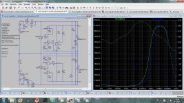
curves from 2sc3503c from bob cordell (green) and bc327 (blue), if you use 2sc3503c in sim you will have much better results , but this transistor is very good , it has a hight early voltage and low noise, but low Hfe , i like it very much , but i think the models are not correct.
Attachments
Dado have you measure your circuit in real life ? Simulations are only as good as the models we use , i tend to use bc327 and bc337 because they give me results close to the reality, if you use the models 2sa1381c 2sc3503c from bob cordell you will have very good distortion results in sim , but not so good in reality.
I did not measure my circuit just I've done some listening with temporary power supply.
Please post LTspice files with all models you use, and I can compare.
You said it is your best result wit current mirrors, or you meant with current conveyor?
Current mirrors convey a current from one side to other with very low distortion.
In my circuit its easy to get a gain of 4 and lower distortion with it.
Be careful with volume control at the output, it will change the gain(it's conveyor).
By the way have you red this thread from beginning, there som more circuit presented?
dado
Kean I have ask Joachim to measure a pair of sanyo 2sc3503 and 2sa the result is here:
http://www.diyaudio.com/forums/analogue-source/154210-mpp-827.html
Very good transistors.
http://www.diyaudio.com/forums/analogue-source/154210-mpp-827.html
Very good transistors.
Correction: should have typed ZVP3306 for the P channel part.Or, short of that, you could use DMOS parts with a few volts of threshold in place of the bipolars. Unfortunately the low frequency noise will usually be higher, and the transconductance lower, compared to the bipolars. Candidates if used might be the ZVN3306 and ZPN3306.
I have change the value of R2 for 500 and 250 ohns to change the gain to 8 and 16.
the results are with 8 X
0.000027% 4 Vp-p out
0.000072% 8 V pp
0.00025% 16 Vpp
with 16X
0.000039%
0.000111%
0.000392%
Even with a gain of 32x the distortion is only 0.000086 at 4 volts p-p out.
It seems that voltage gain is not a problem.
the results are with 8 X
0.000027% 4 Vp-p out
0.000072% 8 V pp
0.00025% 16 Vpp
with 16X
0.000039%
0.000111%
0.000392%
Even with a gain of 32x the distortion is only 0.000086 at 4 volts p-p out.
It seems that voltage gain is not a problem.
Last edited:
Mirror_bjt.asc I have post the models in here already.
Thanks Sergio.
Sergio, I think that your circuit is really excellent demonstration of an engineering skill. I don’t know you but I am glad that you participate in this thread. I know about Keantoken a bit more and followed his fascinating progress in this forum. I am just an old retired telecommunication engineer and audio is my hobby to kip my old gray matter oiled. What I learned more then forty years ago about semiconductors now slowly is coming back and I started to use spice simulator not so long ago.
What do you think if your circuit could be made simpler whiteout loosing to much of its performance, still distortion could stay in ppm region?
Another thing to make it with high gain, let say 20 to 30 dB and then add powerful output buffer to get power amp with no GNFB. I was trying to simulate an output buffer(trying different configuratio) but never was satisfied with distortion level.
Damir
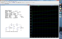
Here is new shuntreg simulation. I am trying to keep just one jfet ccs as in this case output voltage adjustment is possible with one trimer(R7 in this case). Here CCS voltige is 2.2 V and I think its on safe side of the knee(in saturation region).
dado
dado
Attachments
But A and B perform the same when you have 220/75 degeneration. Do you know of a better way to increase gain?
A 220/75 degeneration ratio will imbalance the mirror, and it will lose some distortion cancellation property.
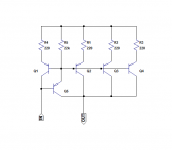
one way to do the job without loosing balance is like this , the penality is adding 2 bjt and 2 resistors.
Attachments
Thanks Damir for your kind words, I'll try to do what you ask , but the components used here are really cheap , the 20 transistors used in this circuit will cost less than a dollar. I do not really see the problem
About the power supply , have you consider The Kmultiplier from Kean, I use a very similar soluction ,It is really very low noise, and have very good stability , and is less complex than the one you are doing. But the output impedance is a bit higher.
About the power supply , have you consider The Kmultiplier from Kean, I use a very similar soluction ,It is really very low noise, and have very good stability , and is less complex than the one you are doing. But the output impedance is a bit higher.
Thanks Damir for your kind words, I'll try to do what you ask , but the components used here are really cheap , the 20 transistors used in this circuit will cost less than a dollar. I do not really see the problem
About the power supply , have you consider The Kmultiplier from Kean, I use a very similar soluction ,It is really very low noise, and have very good stability , and is less complex than the one you are doing. But the output impedance is a bit higher.
Someone said the less is better, and Einstein said " Everything should be made as simple as possible, but not simpler". OK it is question of PCB too, simpler to make.
Regarding power supply, there is oppinion that nothing can beat good shunt regulator and I need to lower power voltage to as mine transformer has 2x30V.
Damir
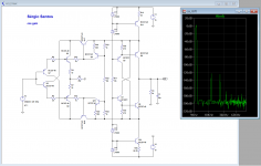
Here is a similar circuit but with current sources instead of current mirrors.
I cut some of the fats, to get it in accordance with Einstein")
The distortion is 0.000069% at 4 V p-p with a gain of 16x
One of the advantages of using current sources like that is that the psrr is higher, I have made circuits with this topology with psrr of 80db.
I cut some of the fats, to get it in accordance with Einstein
The distortion is 0.000069% at 4 V p-p with a gain of 16x
One of the advantages of using current sources like that is that the psrr is higher, I have made circuits with this topology with psrr of 80db.
Attachments
- Status
- This old topic is closed. If you want to reopen this topic, contact a moderator using the "Report Post" button.
- Home
- Source & Line
- Analog Line Level
- Current conveyor as a voltage amplifier