I have download the ltspice file that you post , and have tested , there are alterations that i would like to propose, if you guys do not mind.
First is to lower the voltage , it does not make much sense that hight voltage, you will be ok with minus/plus 15 volts , less power waste. And less thermic problems with the circuit. Other is to change the mirrors transistors (bc550c) with bc327-40 and bc337-40, they should be better in dealing with the current that the circuit use, the distortion will be lower.
The 2sa1381 and 2sc3503 is a very good choice , but the cordell models are a bit to much optimist in respect to early voltage, so expect a litle more distortion in reality that with the simulation, but in the overall it seems a good circuit .
I use current sources instead of mirrors , I get even lower distortion that this circuit post here:
http://www.diyaudio.com/forums/digital-source/217459-dac-i-v-convertion-very-low-distortion.html
Thanks for your suggestions.
I use higher power voltage to get distortion as low as possible with this circuit.
There is low voltage in this thread, simpler and, probably, good enough. One feature important to me was the possibility to drive 300 ohm headphones, not only to be line amp only. By the way, I don't thing that BC337-40 could lower allready very low distortion.
The BC3x7 has a much larger die, so more thermal inertia and less thermal modulation. This is the theoretical basis for its improvement on quality. However it is much slower than the BC560C and while either of these will probably keep measured distortion pretty low, it was my experience in listening tests that the speed of the BC5xx is more important for a small-signal circuit.
At frequencies where R3 and R12 are bypassed, the effectiveness of the J1 CCS will not matter. At DC it will however.
For transient performance, compare the AC current through Q1 and Q2. Lower is always better. Multiply this current by the output impedance and you have a metric for the quality of regulator load response. With this metric you'd find that many regulators have fantastic output impedance but poor transient load response.
You need to consider inductance in absolute terms. Viewing output inductance against the backdrop of output resistance will just show you the proportion of the two. Compare the actual output inductance value to the real inductance of a cm of wire; how many virtual cm of wire does your regulator have?
Same for output resistance. How does it compare to the resistance of the PCB traces? How does the output resistance compare to the standard trace size used for carrying currents of this magnitude?
One think were I have my concern, jfet CCS between Q1 and Q2 bases. In the simulation it looks good, but does 1.3V is enough for 2SK170 to behavs as good CCS at 1.7mA??
dado
A slippery slope
")
Attachments
Adapt your circuit to give similar Zin, Zout and gain and then we can toss boulders.
Early voltage of the A1381/C3503 should not matter if the Baxandall pairs do their job
ok, is fair , i will design a circuit similar to yours but with current sources instead of the mirrors , i like a good challenge
.Baxandall pair will lower distortion produced by the early voltage not eliminate it, the higher the early voltage of the transistor the better, try to swap the 2sa1381c and 2sc3503c with other model in the simulator, and you will see that the distortion increase.
Thanks for your suggestions.
I use higher power voltage to get distortion as low as possible with this circuit.
There is low voltage in this thread, simpler and, probably, good enough. One feature important to me was the possibility to drive 300 ohm headphones, not only to be line amp only. By the way, I don't thing that BC337-40 could lower allready very low distortion.
If you use lower voltage you will get the same distortion, because of the baxandall pair and the cascode at the input (test it ),
the bc550 with that current and voltage will be working in the knee voltage, if you use a bc327/337 you will have lower distortion (test in the ltspice), the bc327 have also a lower base spreading resistance than bc550 (lower noise)
Another reason to use the BC3x7 is that the low base resistance will contribute to better log conformance and thus better current mirror tracking. In theory. However the current mirror emitters already have over 27mV offset owing to the unequal degeneration and this will swamp out any Rb or thermal affects. Considering this discrepancy and that the circuit still performs as well as it does, I wonder if it will make any difference at all whether the BC5xx or BC3x7 are used. However it would be interesting to try and see.
Sometime I want to get hold of some SIP breakaway sockets; this way I can solder them in and keep plugging away with different transistors. I got some 20-pin DIP sockets already which allows for expedient prototyping.
Sometime I want to get hold of some SIP breakaway sockets; this way I can solder them in and keep plugging away with different transistors. I got some 20-pin DIP sockets already which allows for expedient prototyping.
dadod , can you post the ltspice file of the power supply ? I would like to try it.
Here it is. Could you post spice models for BC337/40? In the zip file you'll find all models I am using.
dado
Attachments
A slippery slope
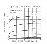
It is simple to get that graph, but my question was about practical experience. I think that 2SK170 should be of GR type.
The BC3x7 has a much larger die, so more thermal inertia and less thermal modulation. This is the theoretical basis for its improvement on quality. However it is much slower than the BC560C and while either of these will probably keep measured distortion pretty low, it was my experience in listening tests that the speed of the BC5xx is more important for a small-signal circuit.
At frequencies where R3 and R12 are bypassed, the effectiveness of the J1 CCS will not matter. At DC it will however.
For transient performance, compare the AC current through Q1 and Q2. Lower is always better. Multiply this current by the output impedance and you have a metric for the quality of regulator load response. With this metric you'd find that many regulators have fantastic output impedance but poor transient load response.
You need to consider inductance in absolute terms. Viewing output inductance against the backdrop of output resistance will just show you the proportion of the two. Compare the actual output inductance value to the real inductance of a cm of wire; how many virtual cm of wire does your regulator have?
Same for output resistance. How does it compare to the resistance of the PCB traces? How does the output resistance compare to the standard trace size used for carrying currents of this magnitude?
Kean, we are no dealing with rocket science here, this looks to me to mutch to go so dip in to PCB traces resistance/inductance.
dado
.model BC327-40 PNP(IS=2.077E-13 NF=1.005 ISE=1.411E-14 NE=1.3 BF=449.8 IKF=0.36 VAF=29 NR=1.002 ISC=2.963E-13 NC=1.25 BR=20.92 IKR=0.104 VAR=10 RB=40 IRB=1.00E-05 RBM=5.3 RE=0.14 RC=0.32 XTB=0 EG=1.11 XTI=3 CJE=5E-11 VJE=0.9296 MJE=0.456 TF=7E-10 XTF=3.25 VTF=2.5 ITF=0.79 PTF=80 CJC=2.675E-11 VJC=0.8956 MJC=0.4638 XCJC=0.459 TR=3.50E-08 CJS=0 VJS=0.75 MJS=0.333 FC=0.935 Vceo=45 Icrating=500m mfg=Philips)
.model BC337-40 NPN(IS=7.809E-14 NF=0.9916 ISE=2.069E-15 NE=1.4 BF=436.8 IKF=0.8 VAF=103.6 NR=0.991 ISC=6.66E-14 NC=1.2 BR=44.14 IKR=0.09 VAR=14 RB=70 IRB=2.00E-04 RBM=8 RE=0.12 RC=0.24 XTB=0 EG=1.11 XTI=3 CJE=3.579E-11 VJE=0.6657 MJE=0.3596 TF=5E-10 XTF=2.5 VTF=2 ITF=0.5 PTF=88 CJC=1.306E-11 VJC=0.3647 MJC=0.3658 XCJC=0.455 TR=2.50E-08 CJS=0 VJS=0.75 MJS=0.333 FC=0.843 Vceo=45 Icrating=500m mfg=Philips)
Thanks for the files.
Last edited:
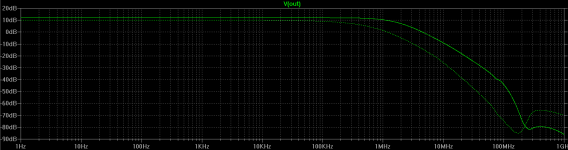
Dado, I gave a quick look at your power supply and it has a very low output impedance indeed, I have to look better, congratulations.
Thanks, but what I did is just to change a bit Borbely(and Salas) shunt regulator.
My point in showing the graph: you can use its data (derive the slope of the curve at your particular operating point) to validate or invalidate your sim model.It is simple to get that graph, but my question was about practical experience. I think that 2SK170 should be of GR type.
If the impedance of the real 170 is too low, one option is to run with two of them, that is, two I generators, with each off of the opposing rail. Make sure to clamp each base-emitter junction with a diode to prevent excessive reverse voltage under a fault condition.
Or, short of that, you could use DMOS parts with a few volts of threshold in place of the bipolars. Unfortunately the low frequency noise will usually be higher, and the transconductance lower, compared to the bipolars. Candidates if used might be the ZVN3306 and ZPN3306.
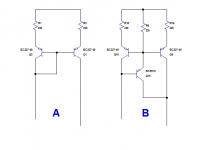
Mirror bjt
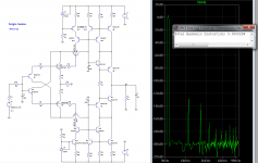
This is the my circuit with mirrors , the distortion (10khz)is :
0,000029% at 4V p-p out.
0,000069% at 8V p-p
0.000219% at 16V p-p.
I must say i never have made a circuit with mirrors with distortion that low.
This is the my circuit with mirrors , the distortion (10khz)is :
0,000029% at 4V p-p out.
0,000069% at 8V p-p
0.000219% at 16V p-p.
I must say i never have made a circuit with mirrors with distortion that low.
Attachments
Last edited:
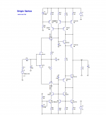
Nice circuits, but with 20(19) transistors and you need output buffer too.
Could you post spice files for both(with all models you used), I would like to make some simulation with.
By the way, I am still playing with the shuntreg to see if I can make it better without more transistor added.
dado
Could you post spice files for both(with all models you used), I would like to make some simulation with.
By the way, I am still playing with the shuntreg to see if I can make it better without more transistor added.
dado
- Status
- This old topic is closed. If you want to reopen this topic, contact a moderator using the "Report Post" button.
- Home
- Source & Line
- Analog Line Level
- Current conveyor as a voltage amplifier