It looks like you have Rout very high. I have it at 2k. For me THD only increased 6db or so at 1V output.
Try moving the diode limiter to Vout2. Then put antiparallel diodes between Vout and Vout2. The antiparallel diodes acts as an output current limit which engages when the voltage limiter conducts. The current limit will engage at 18mA for silicon, 9mA for schottkey. The voltage limiter will cause less distortion because it is now at a low impedance node.
Try moving the diode limiter to Vout2. Then put antiparallel diodes between Vout and Vout2. The antiparallel diodes acts as an output current limit which engages when the voltage limiter conducts. The current limit will engage at 18mA for silicon, 9mA for schottkey. The voltage limiter will cause less distortion because it is now at a low impedance node.
Last edited:
Great!
Thanks Kean for your great help!
Interesting thread.
Have you considered/examined the distortion associated with the buffer amps? In particular, what is the effect of the voltage-dependent Cgd of the input devices on the left? As drawn the source impedance is assumed to be zero except for the effect of C1. Probably, typical line-level sources will be low enough, although not zero.
Buffering the output of the conveyor, on the other hand, will be affected by the relatively high value of its output termination resistor, R1 in the "Clipping4" schematic.
The composite JFET-bipolar feedback pairs will do a pretty good job of bootstrapping out the Cgs at least.
And I like the introduction of base current recapture, as Wurcer calls it (historically, now dating back to F. S. Boxall), which works progressively better as the collector of the auxiliary transistor feeds a higher impedance (in this case the collectors of Q5 and Q7).
Brad
Interesting thread.
Have you considered/examined the distortion associated with the buffer amps? In particular, what is the effect of the voltage-dependent Cgd of the input devices on the left? As drawn the source impedance is assumed to be zero except for the effect of C1. Probably, typical line-level sources will be low enough, although not zero.
Buffering the output of the conveyor, on the other hand, will be affected by the relatively high value of its output termination resistor, R1 in the "Clipping4" schematic.
The composite JFET-bipolar feedback pairs will do a pretty good job of bootstrapping out the Cgs at least.
And I like the introduction of base current recapture, as Wurcer calls it (historically, now dating back to F. S. Boxall), which works progressively better as the collector of the auxiliary transistor feeds a higher impedance (in this case the collectors of Q5 and Q7).
Brad
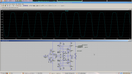
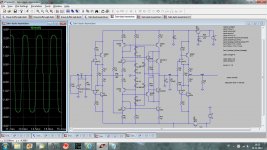
Here is FFT at 1kHz with 100k source impedance. Why do you say "high value of R1", it is just 560 ohm?
Damir
Attachments
I didn't see the value on the one schematic I referenced, sorry.Here is FFT at 1kHz with 100k source impedance. Why do you say "high value of R1", it is just 560 ohm?
Damir
BTW, you are running the JFETs at rather high |Vdg|. In the case of the 2SJ74, the maximum rating is 25V
 Fred Forsell has gotten away with exceeding these ratings in his JFET amps, but agrees that it is risky.
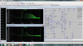
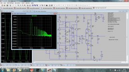
My sims of the first buffer amp driving a comparable resistive load (note that the actual loading by the current conveyor is variable somewhat with signal current and hence will be another distortion mechanism I exclude) show low distortion at 1kHz as well (1V peak, 500 ohm source Z).
Things are still o.k. with 20kHz although the majority of the distortion is now at the input (-112.4dBr input, -112.0dBr output, harmonics included to 9th).
With 10k as the source resistance, the same situation holds with the majority of the distortion due to variable input C (-86.5dBr at input, -86.4dBr at the output). Noted as well: the distortion is primarily 2nd, due to the considerable difference in capacitances between the SK170 and the SJ74.
If one goes about removing most of the gate-drain C effects, performance should improve drastically. With Csanky-style bootstrapped cascoding one can also alleviate the excess voltage issues for the P part. Some small lumped capacitance at the input will probably be needed to reduce high-frequency peaking.
Brad
Walt Jung posted recently about Csanky and gave some references I believe. I'll try to find the post.
Basically, it's just cascoding JFETs and returning the "upper" device's gate to the "lower" device's source. If the latter source is grounded it just becomes a standard JFET cascode, working best when the upper device has a higher pinchoff voltage. When there is impedance in the source then the connection helps more, as the capacitative displacement currents from the upper FET are recycled to some extent and have the effect of reducing the output capacitance (and hence its distortion contribution due to voltage variation) of the upper device.
Basically, it's just cascoding JFETs and returning the "upper" device's gate to the "lower" device's source. If the latter source is grounded it just becomes a standard JFET cascode, working best when the upper device has a higher pinchoff voltage. When there is impedance in the source then the connection helps more, as the capacitative displacement currents from the upper FET are recycled to some extent and have the effect of reducing the output capacitance (and hence its distortion contribution due to voltage variation) of the upper device.
Yes, very much so. I remember puzzling about it initially. Erno typically cascaded SK170s with SK246, SJ74 with SJ103.Oh yes I know it, Borberly used it a lot, is it not?
- Status
- This old topic is closed. If you want to reopen this topic, contact a moderator using the "Report Post" button.
- Home
- Source & Line
- Analog Line Level
- Current conveyor as a voltage amplifier