Looking for some help from you experienced guys out there. I need a simple differential line driver to take a single ended, line level signal to a balanced signal. It is only passing audio signals, but I would like it to be flat up to about 100 kHz.
After reading the specs on the OPA1632, I dug into the TI white paper on differential amplifiers, SL0A54D. Early in the paper, they show this circuit for converting single ended to differential signals.
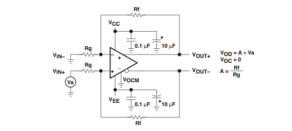
I have had it drummed into my head that "balanced" means balanced impedance. At audio frequencies, the influence of the opamp and feedback on reducing impedance makes this look pretty balanced, even if looking past the opamp to the input is clearly unbalanced.
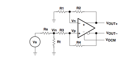
A bit later in the paper, they show this source termination technique for high frequencies.
Question 1
Do I need to do a source termination to stay balanced? If I use a buffer for Vs, then Rs is very small. R3 + Rt ~= R1. If R1 = R3, Rt goes to zero and the circuit starts to look like the first one.
I have also been thinking about putting a small value (200 pF) sliver mica cap in parallel with the feedback resistors. That would kill the gain above 100 kHz, so that high frequency balance wouldn't be an issue.
Question 2
What value resistors should I use in this circuit? It has been suggested that 5 kOhms is a good zone to be in for crossovers. I plan on using equal input and feedback resistors. I'm tempted to use 1 kOhms, but that might increase the need for a source termination. Any thoughts or experience here would be welcomed.
Jac
After reading the specs on the OPA1632, I dug into the TI white paper on differential amplifiers, SL0A54D. Early in the paper, they show this circuit for converting single ended to differential signals.
I have had it drummed into my head that "balanced" means balanced impedance. At audio frequencies, the influence of the opamp and feedback on reducing impedance makes this look pretty balanced, even if looking past the opamp to the input is clearly unbalanced.
A bit later in the paper, they show this source termination technique for high frequencies.
Question 1
Do I need to do a source termination to stay balanced? If I use a buffer for Vs, then Rs is very small. R3 + Rt ~= R1. If R1 = R3, Rt goes to zero and the circuit starts to look like the first one.
I have also been thinking about putting a small value (200 pF) sliver mica cap in parallel with the feedback resistors. That would kill the gain above 100 kHz, so that high frequency balance wouldn't be an issue.
Question 2
What value resistors should I use in this circuit? It has been suggested that 5 kOhms is a good zone to be in for crossovers. I plan on using equal input and feedback resistors. I'm tempted to use 1 kOhms, but that might increase the need for a source termination. Any thoughts or experience here would be welcomed.
Jac
Dont know that I would bother with source termination at anything like audio frequencies (It is mostly an RF tequnique), but a 50 ohm or so resistor in series with each output is a good idea as it both defines the output impedance and decouples the cable capacitance from the opamp feedback loop which helps stability.
Make these resistors close tolerence to maximise low frequency CMRR when run with a poor following stage.
Also some RFI filtering at the output is always a good plan.
Have a look at some of the THAT corp app notes, they are quite useful.
Regards, Dan.
Make these resistors close tolerence to maximise low frequency CMRR when run with a poor following stage.
Also some RFI filtering at the output is always a good plan.
Have a look at some of the THAT corp app notes, they are quite useful.
Regards, Dan.
balanced refers to a differential vs single ended signal. impedance matching is secondary and comes necessarily into play at HF.
source termination is only required for mic pre-amps for noise considerations and HF circuits for reflection issues. note that R1=R3+Rt||Rs and R2=R4 for differential gain and no common mode gain. before shunting the feedback resistor with a capacitor check the manufacturer specs for the phase margin else oscillations may arise.
The min. value of resistors is also dependent on the driving capability of the amp. the max. is limited by the bias currents and offset voltages. a few KOhms is the norm for such audio circuits.
This is completely wrong.balanced refers to a differential vs single ended signal. impedance matching is secondary
You are under the impression that the two voltage signals of a balanced connection must be equal voltage and of opposite phase. This condition is completely unnecessary.
the necessary condition for balanced connection is that the source impedances and the receiver impedances must exactly match and not be influenced by or connected to ground. A transformer did/does this very well. All the electronically derived balanced connection corrupt this by having some reference, albeit usually very small, to ground.
It's the voltages that are secondary or unnecessary.
One voltage can be zero and the other voltage is the signal in a balanced connection. From that you can then add or subtract signal to both phases. i.e. start with 1Vac on cold (-IN) and 0Vac on hot (+IN). Then add 4Vac to both to give 5Vac on cold and 4Vac on hot (still a differential signal of 1Vac), or subtract 500mVac from both to result in -500mVac on hot and +500mVac on cold to again have a dif = 1Vac (- & + indicating 180 degrees of phase difference of the signal).
The opener correctly identified this !
Last edited:
Hi,
Is this circuit needed at all ? Unless the cable is very long converting
to balanced has very little advantage if the single ended source has
decent cable driving capability, see the arrangements here :
Balanced Line Technology
rgds, sreten.
Is this circuit needed at all ? Unless the cable is very long converting
to balanced has very little advantage if the single ended source has
decent cable driving capability, see the arrangements here :
Balanced Line Technology
rgds, sreten.
this is my interpretation of a number of papers from Jung & Self & Whitlock........................the necessary condition for balanced connection is that the source impedances and the receiver impedances must exactly match and not be influenced by or connected to ground. A transformer did/does this very well. All the electronically derived balanced connection corrupt this by having some reference, albeit usually very small, to ground................
If I have misunderstood something as stated above, then please correct me. I would welcome a better understanding of Balanced.
you may have misunderstood my posting. i was referring to differential signals which is slightly different from balanced signals. differential signals require difference of potential and impedances are of secondary importance. on the other hand if someone wants to use a differential amplifier for a balanced system then it indeed it follows that impedances must also be matched. i should have clarified it better from the beginning but i thought it was simple and clear.
You could use this nice circuit from Marcel, it is probably overkill for you, but it does all you need, and more:
http://www.diyaudio.com/forums/soli...alanced-unbalanced-amplifier.html#post3118231
http://www.diyaudio.com/forums/soli...alanced-unbalanced-amplifier.html#post3118231
Thank You All
Between Dan and dacen's suggestions, I am digging into THAT corp application notes and learning something.
Elvee, Thanks. Marcel's design is pretty neat, but as you say, more than I need.
Thanks Demeterart. You are correct, I mis-stated the resistor relationship. I will take your suggestion and check the HF phase margin before adding a shunt capacitor.
Andrew T, Thanks for the clear definition of balanced. It is probably the best one I have read. I will take to heart the suggestion of matching stability component impedances and precision resistors.
I still have a lot to learn from you guys. Thanks again.
Jac
Project Zen
sreten,
You are correct, of course. A good single ended system works just fine. Sometimes, I need to do a project just to learn.
Although my line level run at 4 meters is longer than many single ended runs, it isn't long enough to need a balanced system. But I am doing it anyway, just to see if I can and what it sounds like.
I have a friend with commercially built high end audio equipment that has both single and balanced outputs. He says, he can't tell me why, but he likes the sound better when using the balanced cables.
And, I have already learned something through the input given by others in this thread.
Jac
Hi,
Is this circuit needed at all ? Unless the cable is very long converting
to balanced has very little advantage if the single ended source has
decent cable driving capability
rgds, sreten.
sreten,
You are correct, of course. A good single ended system works just fine. Sometimes, I need to do a project just to learn.
Although my line level run at 4 meters is longer than many single ended runs, it isn't long enough to need a balanced system. But I am doing it anyway, just to see if I can and what it sounds like.
I have a friend with commercially built high end audio equipment that has both single and balanced outputs. He says, he can't tell me why, but he likes the sound better when using the balanced cables.
And, I have already learned something through the input given by others in this thread.
Jac
sreten,
You are correct, of course. A good single ended system works
just fine. Sometimes, I need to do a project just to learn.
Although my line level run at 4 meters is longer than many single
ended runs, it isn't long enough to need a balanced system.
But I am doing it anyway, just to see if I can and what it sounds like.
I have a friend with commercially built high end audio equipment that
has both single and balanced outputs. He says, he can't tell me why,
but he likes the sound better when using the balanced cables.
And, I have already learned something through the input given by
others in this thread.
Jac
Hi,
My point was, if you read the link, there is more than one way
of connecting a single ended output to a remote balanced input,
the simple single ended connection does not take advantage of
the balanced connection at the other end. You can wire the
cable such that is does usefully utilise features of the remote
balanced input without using a fully balanced driver.
Its not simply a case of single ended versus balanced.
rgds, sreten.
A single ended driver with a resistor equal to the output impedance to audio 'ground' for the other leg of the output is a perfectly valid balanced output, it is exactly equivalent to a fully differential output except that the signal level is 6dB lower.
This is **very** common in pro audio and has the advantage that you do not see a 6dB level deficit if plugging an unbalanced load into such a source, of course the downside is effectively 6dB less noise rejection because the differential voltage is 6dB lower.
You will want to look a Whitlocks papers, also the stuff from Tony Walderon is solid on how to do interference free audio on a large scale.
Not quite!
I am asserting that there is no need for a balanced line to be driven differentially to get the benefits.
Balanced is talking ONLY about the impedance to ground so something like an opamp with 50 ohm buildout resistor to pin 2, 50 ohm buildout resistor from circuit 0V to pin 3 and pin one bonded directly to chassis is a perfectly valid balanced line output (Omitting the RFI and P48 protection details), and assuming standard XLR pinning.
Making it differential gets you 6dB more voltage on the line of course, but you can get most of the way there with a single extra resistor at the sending end, the receiver does of course still need to be a differential input.
Whitlocks AES lecture explaining balanced lines in terms of a wheatstone bridge is worth looking out (The slides are available on line).
Regards, Dan.
- Status
- This old topic is closed. If you want to reopen this topic, contact a moderator using the "Report Post" button.
- Home
- Source & Line
- Analog Line Level
- Differential Line Driver - Impedance Questions