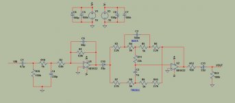
C10 is the DC block for the bass cut lowpass though, yeah, it could also be implemented as a shelving filter. It's common to AC couple guitar gear on both input and output just in case the next gizmo in the chain doesn't adhere to the AC coupling convention. So C11 is optional but conventional. R12 is the usual source impedance pad to move the capacitive load pole far enough down in frequency that the op amp remains stable.Is R12 necessary? You'll have a high input impedance at the next stage, so I can't see 100 ohms making much difference. And unless DC offset is a problem, C10 & C11 aren't needed.
Sounds like tone suck. The 5532's a perfectly fine audio op amp when used appropriately but at 30k min, 300k typ it has an unusually wide input impedance range. Check the impedance matching; wouldn't surprise me if you got a 5532 on the low corner and the circuit's dragging. If so, a quick fix may be to switch from bipolar (the 5532's built using BJTs) to a process with higher input impedance. The Jfet TL072 is a common choice for its teraohm input inpedance, low cost, and decent performance.Bypassing the contraption entirely, made a HUGE improvement.
Looks fine to me (though I didn't sim the circuit and do a noise analysisI would like your comments...
") ). The second order ~450kHz lowpass around U1 is arguably overkill---first order and using U1 as a buffer would be fine too. Either way I'd probably corner it more like 50-100kHz; no need for the extra bandwidth so it's just more noise susceptibility.
). The second order ~450kHz lowpass around U1 is arguably overkill---first order and using U1 as a buffer would be fine too. Either way I'd probably corner it more like 50-100kHz; no need for the extra bandwidth so it's just more noise susceptibility.As an aside, I think this thread should be in the instruments and amps forum.

Having started re-reading Cordell's book, I think Cordell will argue very strongly that R12 @ 100r is very necessary to interface with the following cable/interconnect.
There may be good logic for reducing the value to 75r, or 50r, if coax, of those characteristic impedances, were to be used for interconnect, but the 100r value would be good for a twisted pair interconnect.
There may be good logic for reducing the value to 75r, or 50r, if coax, of those characteristic impedances, were to be used for interconnect, but the 100r value would be good for a twisted pair interconnect.
I would, too. [Originally] Being in the Chip Amp forum made me answer in an integrated amp context. I'm still holding to my C10-C11 comments. What are your thoughts on R11? Would a smaller value matter at all, yet still provide isolation?I think Cordell will argue very strongly that R12 @ 100r is very necessary to interface with the following cable/interconnect
Well, and now yours too.twest820, the only post in this thread mentioning guitars is yours.
Electric guitar rigs tend to wind up with three or four high+low tone controls plus a few mids and some highs---the majority of guitars, amps, and effects pedals have them. I also know harpists, keyboard, and violin players who use tone stacks in pedal form. Whereas my experience is most preamps don't have tone controls. You are correct I shouldn't have been so quick to assume an instrument application but hey, if pinkmouse is happy I'm happy.The input impedance as viewed by the source is only 6.8k. 10 K is a convention minimum, and I usually design for 50K, so the source is less likely to be distorted by driving too heavy a load. Besides potentially causing distortion, you're likely to lose bass if the output cap on the source isn't big enough.
100-200 ohm resistors at the output of an opamp circuit is wise for stability. Linkwitz and all the engineers at Dolby Labs use them. The rolloff they cause is way out in frequency. I've designed and built many of these tone control circuits and used 50KB pots, which generate more noise than 10k, but it's not a problem, and it makes life easier on the opamps (less distortion).
I'd definitely get rid of all the electrolytics and use polyprop or polystyrene caps instead. On the power supply, I'd use electrolytics bypassed with 0.1uF polyprops. Put the bypass caps within an inch of every opamp.
Opamps can be stellar when they are stable (no spurious oscillations), and when they are not asked to do something they can't do well. I always put a passive Rf filter at the input of any opamp circuit, cutting off above about 50kHZ, to accomodate this. Digital sources usually put out energy well above the audio spectrum, which most opamps can have trouble with. If the application is a guitar amp, I'd set the frequency no higher than 15kHZ, since any guitar acts as an antenna and will bring significant Rf into the system, causing slewing related distortions and beat frequency noise in the audio spectrum.
In the case of feeding into the inverting input of an opamp (as you are doing - so the circuit as a whole in non-inverting), I would split the input resistor into two parts that add up to the value you want, and hang a mica, polyprop or polystyrene cap to gnd right there to create the passive input Rf filter. When calculating the value of the cap, it's a matter of what resistance the cap sees looking out into the circuit.
Tone controls are always a good thing when done well. If bypassing them sounds better, the design is bad. Hope this helps.
Last edited:
Tone controls are always a good thing when done well. If bypassing them sounds better, the design is bad.
A very well said thing ...Also choice and quality of caps will play some role in the tonal response and ""Picture"" aim for less db but nice coloration..
Kind regards
sakis
A very well said thing ...Also choice and quality of caps will play some role in the tonal response and ""Picture"" aim for less db but nice coloration..
Kind regards
sakis
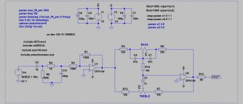
R1 and R2 are high with respect to noise and noise pickup but if you need 100k input impedance...
R8 should be on the other side of the cap. The opamp DC conditions are already defined by the feedback and + input ground reference.
If it is withinn the opamps driving capacity then reducing the impedance of tone network might help with noise. How audible the noise would be is another matter though, it won't be high anyway.
(didn't study your other power amp as its quite an involved and time consuming exercise )
R8 should be on the other side of the cap. The opamp DC conditions are already defined by the feedback and + input ground reference.
If it is withinn the opamps driving capacity then reducing the impedance of tone network might help with noise. How audible the noise would be is another matter though, it won't be high anyway.
(didn't study your other power amp
as its quite an involved and time consuming exercise )- Status
- This old topic is closed. If you want to reopen this topic, contact a moderator using the "Report Post" button.
- Home
- Source & Line
- Analog Line Level
- NE5532 Tone Control