I am a EE student but I am a newbie of audio design.
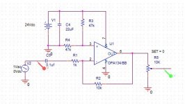
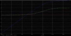
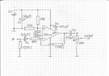
I just simulated this typical preamp circuit but the frequency response looks bad.
my idea is connect this preamp to a tone control circuit, then to the LM3875 power output.
attached the result of Pspice simulation.
I just simulated this typical preamp circuit but the frequency response looks bad.
my idea is connect this preamp to a tone control circuit, then to the LM3875 power output.
attached the result of Pspice simulation.
Attachments
The main problem is simple... the choice of opamp. The 741 is utterly and totally outclassed performance wise and has been for the last 35 years or so ") But its great for learning.
But its great for learning.
Your first circuit has a voltage gain of 100 and that means the gain of the 741 rolls off very early. The second circuit has a gain of 10 and uses a very decent OPA134. You could use that for all these circuits.
Your second opamp circuit also has another problem that the first one doesn't. Can you see what it is ?
But its great for learning.Your first circuit has a voltage gain of 100 and that means the gain of the 741 rolls off very early. The second circuit has a gain of 10 and uses a very decent OPA134. You could use that for all these circuits.
Your second opamp circuit also has another problem that the first one doesn't. Can you see what it is ?
The main problem is simple... the choice of opamp. The 741 is utterly and totally outclassed performance wise and has been for the last 35 years or so
Your first circuit has a voltage gain of 100 and that means the gain of the 741 rolls off very early. The second circuit has a gain of 10 and uses a very decent OPA134. You could use that for all these circuits.
Your second opamp circuit also has another problem that the first one doesn't. Can you see what it is ?
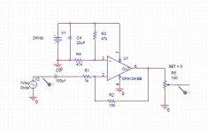
oh Im sorry I didn't wrote the topic clear. The LM741 circuit and the tone adjust circuit are taken from some audio website. I changed the opamp to the OPA134. Now I change the coupling capcitor to 100uF and the Low freq response is better. How do I determine the suitable coupling cap without simulation?
Attachments
I just spotted something else. Normally when talking of poor response and the 741 we mean at HF but you have a problem at LF too. The input coupling caps are far to small in relation to the 1K input impedance. Try a 10uf instead of the 0.1uf.
Thank you. how do u know the input impedance is 1K?
Thank you. how do u know the input impedance is 1K?
oh I am so dumb. It is just an active high pass op amp circuit and Vout/Vin = 10k/(1k +1/jwC).
The input impedance is 1k which is rather low for most purposes, you don't say what it is intended to amplify.
A major difficulty with this circuit is that at the usual 47-100k input impedance general purpose pre amp the series resistor contributes a large amount of noise.
To calculate an input capacitor just transpose, r = 1/(2pifC).
rcw
A major difficulty with this circuit is that at the usual 47-100k input impedance general purpose pre amp the series resistor contributes a large amount of noise.
To calculate an input capacitor just transpose, r = 1/(2pifC).
rcw
The input cap should be 2uF2, i use tantalum here. Input impedance should be 10K or 47K for phono. Use NE5532 opamp, this is an industry standard.
Mac
The Book Worm - DIY Audio Ebooks and Manuals - Speakers, Moscode Amplifiers, Electronics, Map Reading, Free Capacitor Intro.
Mac
The Book Worm - DIY Audio Ebooks and Manuals - Speakers, Moscode Amplifiers, Electronics, Map Reading, Free Capacitor Intro.
The input cap should be 2uF2, i use tantalum here. Input impedance should be 10K or 47K for phono. Use NE5532 opamp, this is an industry standard.
Mac
The Book Worm - DIY Audio Ebooks and Manuals - Speakers, Moscode Amplifiers, Electronics, Map Reading, Free Capacitor Intro.
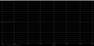
Yeah the response is very similar to using 1k and 100uF. Fc = 1/2*pi*R*C is so right. I am going to use this to amplify signal from a Bluetooth module btw.
Just for info i use this as a virtual earth input buffer on my Camm EquiTone preamp with gain set at about 2. Works well with the TA7630p that follows, better than any tone control.
Mac
DIY Preamplifier - The Book Worm
Mac
DIY Preamplifier - The Book Worm
<quote>The LM741 circuit and the tone adjust circuit are taken from some audio website.</quote>
WRONG! The second circuit was stolen from my site ( sound.westhost.com ) and is reproduced here without permission.
Moderator - please remove the image from my site from this thread - I am sick and tired of people stealing my drawings without permission or even the common courtesy of acknowledgement.
hello.
here is a schematic with optional parts......
wow thank you!
- Status
- This old topic is closed. If you want to reopen this topic, contact a moderator using the "Report Post" button.
- Home
- Source & Line
- Analog Line Level
- What's wrong with this typicial preamp circuit?