Actually having read the standards for immunity as it applies to audio kit, I would love them to be much, much tougher, the EMC regs are a massive compromise where the manufacturers have sucessfully argued for a somewhat loose standard on cost grounds (Pay particular attention to the amount of degridation that is allowed to still be considered a pass).
In a metal cased device, AES48 is pretty much conventional grounding, it can still have a star point it is just that the screen is NOT considered to be a signal conductor and is considered to be an extension of the faraday cage formed by the case, in that context connecting it to the case as directly as possible at the connector only makes sense.
Unlike having to get all sorts of clever when it comes to hooking things up, it actually just works (Usually first time).
Things are one hell of a lot better now then they were, and car ignition noise coming out of your hifi is mostly a thing of the past (I would hope), but cell phones getting into random audio kit is still far too common, and I still find myself chasing earth loops in situations where they should be irrelevant (And where I would rather be in the bar!), because someone still does not get common impedance coupling.
A 2M handheld (Maybe a few watts ERP on 144MHz) in a hifi show can still cause most amusing chaos, and it **REALLY** should not even be noticed.
I don't know where the signal cable catching fire came from, but I have actually seen it once it was a DMX line and there had been a catastrophic fault in some megawatt (Literally) class three phase distribution gear, basically the screen ended up carrying the entire neutral current for the dimmer installation (This was between buildings and had been rather badly thought out).
Regards, Dan.
The main problem is the EMC regulations, they are completely over exaggerated! To comply, your equipment have to withstand RF levels which will not occur in 99,99% in normal use. And I have never seen a burned signal cable........ Power cables yes, plenty
Many others also feel the the newest EMC regulations are over the top. Solving problems that don't exist.
I have been working in the Pro Audio world for 30 years, never had a single problem with the "old" grounding method.
Luck was on your side. In the US Neil Muncy, Bill Whitlock, Jim Brown & Henry W. Ott have shown time and time again the bad results of pin #1 problems.
Thanks man. If you do the same for the THAT1200 series I'll be happy the same.I made a pcb design for the That 1646 balanced line driver...
[EDIT]
BTW, are there any issues related to higher DC offset when just strapping C5~C8?
Last edited:
Hi guys
I try to select the recommended ferrite beads on my own, but as a poor electronics newb I'm a little huge puzzled: please what should I use therein to filter RF 3-band GSM like stated in the 1646 datasheet? http://www.murata.com/products/catalog/pdf/c30e.pdf BL1-BL2-BL3? They say page (viewer 5 - internal 3) they suit from few MHz to few GHz. Is it OK? I can't understand why the 20 p/n against the only 4 spec curves on page 10.
For EMI/surge suppression side I selected for 1206/1646 this small bridge Vishay DF10M-E3 and zeners BZX79-B12 for the 1206... ok too?
Thank you for help. I'll publish the PCBs here when it's done
Bye bye
I try to select the recommended ferrite beads on my own, but as a poor electronics newb I'm a little huge puzzled: please what should I use therein to filter RF 3-band GSM like stated in the 1646 datasheet? http://www.murata.com/products/catalog/pdf/c30e.pdf BL1-BL2-BL3? They say page (viewer 5 - internal 3) they suit from few MHz to few GHz. Is it OK? I can't understand why the 20 p/n against the only 4 spec curves on page 10
.For EMI/surge suppression side I selected for 1206/1646 this small bridge Vishay DF10M-E3 and zeners BZX79-B12 for the 1206... ok too?
Thank you for help. I'll publish the PCBs here when it's done
Bye bye
Balancer AND unbalancer
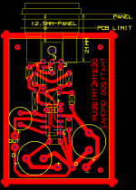
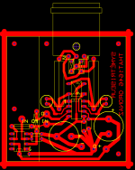
Hi guys, here is the job for DIYers, with RF & EMI protections like in THAT datasheets. Ferrite beads I selected are 2661023801 from Fair-Rite, zeners BZX79B-12 and protection diodes on both PCB are Vishay's bridge 1000V/1A with relatively low leakage DF10M-E3 for availability.
There is an optionnal OPA227/8 input amp on the line driver you can cut out if not usefull, or keep and possibely adjust gain.
Some optionnal components are not mounted (the ones with a cross insde) or replaced by a strapp (the ones with a straight line inside): refer to datasheet.
Guys, is my design "Pin-1 problem" free?
bye bye
Attachments
I made a pcb design for the That 1646 balanced line driver. I posted it on the dutch Zelfbouwaudio forum and Kostas alias TheShaman found it and contacted me if I had some spare pcb's.
I will post here some pictures, the schematic and gerber files so everybody can order the pcb's at for example Itead.
Hi ds23man,
I am interested in you PCB for the THAT 1646 balanced line driver.
I would be looking for 20 such PCB's, would you be able to give me some more information on them please?
I am not used to forums, so could you e-mail me the details, please?
my e-mail address is ccolandjan@tiscali.co.uk
with many thanks,
Colin.
Hi guys, here is the job for DIYers, with RF & EMI protections like in THAT datasheets. Ferrite beads I selected are 2661023801 from Fair-Rite, zeners BZX79B-12 and protection diodes on both PCB are Vishay's bridge 1000V/1A with relatively low leakage DF10M-E3 for availability.
There is an optionnal OPA227/8 input amp on the line driver you can cut out if not usefull, or keep and possibely adjust gain.
Some optionnal components are not mounted (the ones with a cross insde) or replaced by a strapp (the ones with a straight line inside): refer to datasheet.
Guys, is my design "Pin-1 problem" free?
bye bye
Hi HumnSmoke,
Is it possible to purchase the PCB's from you directly? The one I am interested in is the version with the OPA227/8 gain setting op-amp.
I am located in the UK.
Many thanks,
Colin.
Hi Colinh
I don't sell pcbs. Instead I get them made by my local electronic shop here in south-west France.
WARNING: there seems to be an error in my driver 1646 PCB at the OPA227 traces (input pins swapped together and feedback resistor misplaced: the pcb "seemed" to work when used with unity gain OPA227 wiring... I still don't know why; ) Give me some days to correct it)
Sorry
I don't sell pcbs. Instead I get them made by my local electronic shop here in south-west France.
WARNING: there seems to be an error in my driver 1646 PCB at the OPA227 traces (input pins swapped together and feedback resistor misplaced: the pcb "seemed" to work when used with unity gain OPA227 wiring... I still don't know why
; ) Give me some days to correct it)Sorry
Last edited:
Inputs are not swapped. Unity gain at OPA227 as worked as is. The error is in feedback resistor when-used-instead-of-a-strapp (OPA227 with gain>1) misplaced/mistraced/misrouted: in this case you find the 1646 input (pin4) linked to OPA227 inverting input instead of output.
As said give me some hours/days to correct this. The steven2992 guy I forked the ideas from THAT 1646 unbalanced to balanced line driver also added a 100k to ground on OPA227 input, whose necessity depends on whether you may have this input floating or not.
As said give me some hours/days to correct this. The steven2992 guy I forked the ideas from THAT 1646 unbalanced to balanced line driver also added a 100k to ground on OPA227 input, whose necessity depends on whether you may have this input floating or not.
"...you may have this input floating or not..." also/mainly means unplugged, although equivalent situation may happen with unpowered circuitry before the OP am, depending on it's unpowered output impedance... I'd rather add this 100kΩ resistor... after I check the datasheet...
You may ask my supplier: Nous contacter - DISTRONIC SARLHi ds23man,
I am interested in you PCB for the THAT 1646 balanced line driver.
I would be looking for 20 such PCB's, would you be able to give me some more information on them please?
I am not used to forums, so could you e-mail me the details, please?
my e-mail address is ccolandjan@tiscali.co.uk
with many thanks,
Colin.

Don't forget (as I did ) this PCB doesn't provide any trace from supply 0V to input 0V. This is intended to prevent any hidden ground loop.
So if your design carefully isolates input jack ground from chassis or any other ground, think to connect the input ground of this PCB to the 0V of its supply.
) this PCB doesn't provide any trace from supply 0V to input 0V. This is intended to prevent any hidden ground loop.So if your design carefully isolates input jack ground from chassis or any other ground, think to connect the input ground of this PCB to the 0V of its supply.
- Status
- This old topic is closed. If you want to reopen this topic, contact a moderator using the "Report Post" button.
- Home
- Source & Line
- Analog Line Level
- That 1646 balanced line driver PCB