Thanks Carl,
I am hoping that you will like the result and that you will find the overall tonal texture of the sound to be clean without any unpleasant coloration.
kind regards,
Harrison.
I am hoping that you will like the result and that you will find the overall tonal texture of the sound to be clean without any unpleasant coloration.
kind regards,
Harrison.
Great! I am looking forward to seeing them.
Hi Carl,Harrison,
I have received your PCBs, thank you for that! I'll check my parts bin and do my best to put one together over the upcoming holiday weekend.
Pleasure, sorry have just seen this, busy month
")
kind regards,
Harrison.
I am interested if the board is still available.
best regards
Zoky2
Hi Zoky2,
Sure no problem. Thanks for joining us. PM your shipping address
kind regards,
Harrison.
.
This has been nagging at me so I decided to jump in.
In post #1, referring to the "LEVEL" control, which is the 50k pot connected to the non-inverting input of X1.
The bias current for X1's non-inverting input is drawn through this pot, which as shown might be any value from zero ohms to 50k.
I'm guessing you're depending (reasonably) on the very low bias current of the OPA134 to keep this from being a problem. Or otherwise might not the varying voltage drop across LEVEL cause problems with the operation of the OPA134 itself?
.
Last edited:
Hi Zrxshack
Thank you for joining. PM your shipping
kind regards
Harrison.
Thank you for joining. PM your shipping
kind regards
Harrison.
Hello OnAudio,
I am very interested. Are there any boards available?
Shack
Hi bentsnake
The DC will vary in the pV or nV range. The published offset max of OPA134 is in the mV range and the noise in nV range. The DC tracking capabilities of the chip should be okay.
Carls review is on the home stretch
kind regards
Harrison.
The DC will vary in the pV or nV range. The published offset max of OPA134 is in the mV range and the noise in nV range. The DC tracking capabilities of the chip should be okay.
Carls review is on the home stretch
kind regards
Harrison.
.
This has been nagging at me so I decided to jump in.
In post #1, referring to the "LEVEL" control, which is the 50k pot connected to the non-inverting input of X1.
The bias current for X1's non-inverting input is drawn through this pot, which as shown might be any value from zero ohms to 50k.
I'm guessing you're depending (reasonably) on the very low bias current of the OPA134 to keep this from being a problem. Or otherwise might not the varying voltage drop across LEVEL cause problems with the operation of the OPA134 itself?
.
The DC will vary in the pV or nV range. The published offset max of OPA134 is in the mV range and the noise in nV range. The DC tracking capabilities of the chip should be okay.
Thanks for your reply, Harrison. Yep I thought so,but wanted to check.
.
 Congratulations on being the first to give feedback on the P1 on this forum
Hello all,
I have built the default version of the P1 Preamp. It works well. I use a pair of Sennheiser 650 headphones when critical listening to line gear. The preamp is very neutral, adding no color that I can detect. The tone controls are subtle but appropriate. I used Alpha pots with center detents for the tone controls. This is a very inexpensive project to build. The circuit measured flat within a half dB when they were centered. Noise performance and distortion are near the limits of my bench gear. However if you were to revisit the layout I would suggest that you put a little more space between the components as some are tight. That could be done without increasing the size of the PCB. And if it were me I would swap the physical placement of the overall volume and channel trim controls. When I reach for the volume I always end up at the wrong end! The usual convention is to have the volume control to the right.
Also I recommend that you combine the channel trim controls into a dual pot (flipping the left channel) converting your trims into a balance control. I also am toying with the idea of ordering a GoldPoint attenuator to put in place of the volume control. I will most likely make these mods to the 2nd PCB that you sent me and put the results in a nice case. Over the upcoming holidays I plan to swap out the OPA2134s for some 'so called audiophile parts' that I have on hand and see if I can hear a difference. Hopefully I should have time during the holidays to take some PICs as well. And please be certain to not take my comments as critical. On the overall your design shows well. My suggestions are just that. Please discount them at will.
Hi Carl,
True, in most equipment the volume is to the extreme right. The idea behind the layout is that the oftenly used control being the volume would be readily accessible the the extreme left. The order of controls indicates the frequency of use. Once you set up your level and bass/treble boost or cut, then what remains for you to play around is the volume control. Indeed it be tight probably with benefits All this could be addressed in a later layout of the PCB.
Am glad that the PCB turned out transparent making the preamp coupled with the selection of components allowing the noise and distortion specifications of the OPA2134 to dominate It will be interesting to note the added benefits that hi-end op-amps will bring coupled also with gold point attenuators, definitely there will be benefits (at a cost ) The Sennheisers min impedance of 300 ohms, coupled with the output resistor of 100 ohms brings the load total to the OPA2134 at 400 ohms, which is probably pushing it for the chips whose specs have been taken between 600 ohms and 2000 ohms. The 100 ohm output resistor versus the Sennheisers 300 ohms means that the OPA2134 is not maintaining an iron fist grip over Sennheisers, but still maintains a factor of control, making the headphones probably sound carefree and musical which am interpreting to mean sounds neutral . This is a refreshing angle to this preamplifier. The preamp was developed as a line amplifier to nudge out/suppress the bass as need be without over coloring the bass presence as well as color the treble region adjusting the spice and salt as the situation appeals. Looking forward to your feedback on line level usage of the preamp also.
Your selection of center detent for bass and treble control are a smart choice. Good job.
kind regards
Harrison.
True, in most equipment the volume is to the extreme right
. The idea behind the layout is that the oftenly used control being the volume would be readily accessible the the extreme left. The order of controls indicates the frequency of use. Once you set up your level and bass/treble boost or cut, then what remains for you to play around is the volume control. Indeed it be tight probably with benefits All this could be addressed in a later layout of the PCB.Am glad that the PCB turned out transparent making the preamp coupled with the selection of components allowing the noise and distortion specifications of the OPA2134 to dominate
It will be interesting to note the added benefits that hi-end op-amps will bring coupled also with gold point attenuators, definitely there will be benefits (at a cost ) The Sennheisers min impedance of 300 ohms, coupled with the output resistor of 100 ohms brings the load total to the OPA2134 at 400 ohms, which is probably pushing it for the chips whose specs have been taken between 600 ohms and 2000 ohms. The 100 ohm output resistor versus the Sennheisers 300 ohms means that the OPA2134 is not maintaining an iron fist grip over Sennheisers, but still maintains a factor of control, making the headphones probably sound carefree and musical which am interpreting to mean sounds neutral . This is a refreshing angle to this preamplifier. The preamp was developed as a line amplifier to nudge out/suppress the bass as need be without over coloring the bass presence as well as color the treble region adjusting the spice and salt as the situation appeals. Looking forward to your feedback on line level usage of the preamp also.Your selection of center detent for bass and treble control are a smart choice
. Good job.kind regards
Harrison.


Good idea, what am toying around with is having the dual pot, but maintaining another pot (probably trimmer) for balanceAlso I recommend that you combine the channel trim controls into a dual pot (flipping the left channel) converting your trims into a balance control.
kind regards
Harrison.
New updates
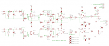
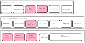
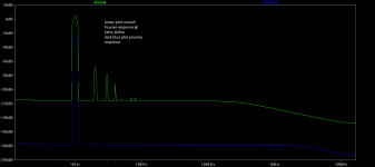
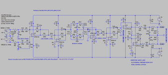
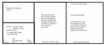
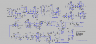
Attached is the P3 and P4 integrated and external preamplifiers, with attached charts from 1diffqc power amplifier. Also attached is a note from Texas Instruments http://www.ti.com/lit/pdf/tidu034 as you will note the Baxandall (1980) active volume control is in use in the note as well as low value resistors, included a TVS diode.
The paths taken in these two designs was slightly different
Attachments
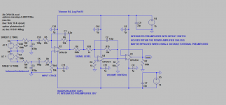
Are AC 1 V1 & AC 1 V3 the balanced impedance audio signal?
If so, then the RF attenuation (C3 & C4) should be connected back to the Chassis socket or to Pin1 and thence to chassis/enclosure. This should be done as close to the chassis socket as possible.
Do not bring the RF interference along wires that can re-radiate EMI into other internal receivers.
I suggest that R27, R8, C3 and C4 be fitted to the input socket, not to the internal wiring.
- Status
- This old topic is closed. If you want to reopen this topic, contact a moderator using the "Report Post" button.
- Home
- Source & Line
- Analog Line Level
- P1 preamplifier