I have enclosed the exponential circuit that "worked" best in the simulations. There is room however for better dimensioning.
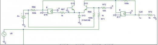
The working principle is that the exponential relationship of base current and base voltage of Q13 is used to caues an output voltage from E17. The voltage sources are set to a gain of 80 dB and are therefore quite good approximations of OP-AMPs. R68 is there to bias the circuit such that the base voltage doesn't get negative during the lowest point of the negative going halve-waves of the input signal.
Q12 and E16 are there to set the bias for Q13 and for thermal compensation. This part of the circuit might have a tendency for oscilations in real-life. This could be solved with a cap from the output of E16 to its inverting input (i.e. the classic dominant-pole compensation).
Any small-power NPN should work. Just take care that they are of the same type and that they are thermally coupled (and no don't directly solder metal-can types together as most of them have their collector connected to the can).
I think it sholdn't be a bog problem to design the filter and summing stages. At least not the circuit itself. Finding the best filter cutoff frequencies might be a matter of trial and error and of course personal taste.
In a few weeks I will have some more time and probably try it on a DSP. I play ERB and will probably make some sound samples if the effect is worth it.
Regards
Charles
Attachments
Last edited:
the component values depend upon what device you use and what Voltage you run it at.
I haven't had chance to build a breadboard version yet but mine will be run from a split supply and used mains powered, so battery life is not an issue, the 074 is also a device that draws more quiescent current than you would desire for battery operation, but I have a supply on hand and use them in test instrumentation..
rcw
This is the one I will be committing to breadboard..
The filter and the mixed in level are adjustable in this to allow adjustment for the best subjective effect.
rcw
. Edit:- The shunt capacitor should have a value of 4n7, not the on on the diagram.
The filter and the mixed in level are adjustable in this to allow adjustment for the best subjective effect.
rcw
. Edit:- The shunt capacitor should have a value of 4n7, not the on on the diagram.
Attachments
Last edited:
Oh yeah, that's a good test. Big extended range bass meets. . . little speaker.ERB = extended range bass
Regards
Charles
")
An analog multiplier is basically an AGC circuit. It is an amplifier who's gain (multiplier) is set by a control voltage. An AM modulator is also one. It does this using analog components rather than digital logic.
Logarithmic amplifiers can be used to construct an analog multiplier by putting an anti-log amp after a log amp and then adjusting the offset of the log amp.
Logarithmic amplifiers can be used to construct an analog multiplier by putting an anti-log amp after a log amp and then adjusting the offset of the log amp.
This one is for full bandwidth: http://www.diyaudio.com/forums/atta...rs-jan-meier-psychoacoustic-bass-enhancer.pdf
Most of the others will work fine with a woofer-only amplifier, such as subwoofer or the woofer amp of a bi-amp system.
It is also possible to use a DSP or simply purchase some Philips desktop speakers that have the tech inside.
As for my own portable project (involving the need of hearable low bass from little speakers), I moved and the project stalled out. . . except that recently I got TDA8932 amplifiers, that have the wide voltage tolerances needed for a solar powered portable outfit.
Thanks.
I was hoping you had completed the smaller project, and was looking for details on that. Too bad the project never made it to completion.
The full bandwidth design is much more than I'm looking to get involved with.
If you ever make any progress on the more basic project, it'd be great if you could share your design schematic.
This is a simulation of the circuit I posted early in this thread.
As configured with the 40Hz. sine wave input shown it produces even and odd harmonics, the odd harmonic production is due to C6.
This can be left out, the result being only even harmonics, a capacitor can be put across the rectifier in which case a smaller amplitude of odd harmonics is produced.
U4 is a low pass filter the Q of which can be altered by C3.
Since the harmonics are then mixed with the original signal it is wideband, and considerably simpler than the Meier circuit and is very flexible.
rcw
Attachments
Can you post an enlargement of the circuit, showing resistor values and a useful op-amp? Did I see an op-amp on there? I'm not sure. Maybe it was my imagination; so, if there wasn't supposed to be an op-amp on there, no need to add one. I just can't see the details--picture is too tiny.This is a simulation of the circuit I posted early in this thread.
As configured with the 40Hz. sine wave input shown it produces even and odd harmonics, the odd harmonic production is due to C6.
This can be left out, the result being only even harmonics, a capacitor can be put across the rectifier in which case a smaller amplitude of odd harmonics is produced.
U4 is a low pass filter the Q of which can be altered by C3.
Since the harmonics are then mixed with the original signal it is wideband, and considerably simpler than the Meier circuit and is very flexible.
rcw
C3? Is that how we keep harmonic mods away from the voice band? I can't really see a C3 in the little photo, because blurry, but the description of it does seem inviting.
I hope you can see this.
The circuit uses a quad opamp, the 074 type should do it. As shown it is configured for a dual rail power supply but can be adapted to a single rail if required.
Note that this is an ltspice circuit simulation and not a final practical circuit guaranteed to work first time etc.
rcw
The circuit uses a quad opamp, the 074 type should do it. As shown it is configured for a dual rail power supply but can be adapted to a single rail if required.
Note that this is an ltspice circuit simulation and not a final practical circuit guaranteed to work first time etc.
rcw
Attachments
Thank you! That photo is nice and clear.
A netbook's screen is 600 pixels tall, or a modern desktop is 1080 pixel height.
Your image with 2 colors and 578 pixel height is Very close to optimal for schematics, because it is readable on all computer screens.
It would be 1/6th of the bandwidth consumption in 2-color .gif format (it would be 11k).
This thread goes on confusing me.
How can we fake bass.Low frequencies are more air,More cone movement ,more current consumption.Can we fool the loudspeakers.If yes what kind of plan we have?
Any reference models which already uses Psychoacoustic Bass?
Usually boomy monotone or boom boxes are not at all entertaining.They sound boring after a minutes of listening.
What we are doing is fooling your ear by exploiting the missing fundamental effect.
In the circuit I posted for instance it shows a 40Hz. sinewave going in, and the harmonics of this coming out with the fundamental greatly attenuated.
If you play this back to people, they in general cannot tell that the fundamental has gone and only the overtones remain, this is the psychoacoustic effect.
This can make small low powered speakers sound as though they have some low bass output.
rcw
Right on!What we are doing is fooling your ear by exploiting the missing fundamental effect.
In the circuit I posted for instance it shows a 40Hz. sinewave going in, and the harmonics of this coming out with the fundamental greatly attenuated.
If you play this back to people, they in general cannot tell that the fundamental has gone and only the overtones remain, this is the psychoacoustic effect.
This can make small low powered speakers sound as though they have some low bass output.
rcw
These days, the usual speaker is in the range of 0.5" to 4" at best; and, if you happen to have a bass guitar, I'd still like to hear it.
Well, would you rather have a floorboard flavor diet cola or would you rather have a Tab at 3x the cost? They are still made, but serving up the point (deliciously), the market for quality is still short.
The majority of the available market does not own speakers with enough size to reproduce the bass guitar.
- Status
- This old topic is closed. If you want to reopen this topic, contact a moderator using the "Report Post" button.
- Home
- Source & Line
- Analog Line Level
- Ultrabass, psychoacoutstic low bass for little speakers