Hello everyone!
I am a long time lurker who finally decided to make his first few posts. I have many projects I am working on concurrently, but with any luck I will be using this one in several of my other projects. Without further ado, onto the project description!
(I copied/pasted most of this from my intro post)
-Configurable active crossover-
About a year ago we had someone give a rather sizable donation to our hackerspace which included LOTS of audio paraphernalia including a small mountain of discreet components. The vast majority of which are of relatively high precision (1-3%). We sorted through the mess and finally got it organized only to find that most of the stuff wasn't really useful to us. So after a year I got permission to take a bunch of the parts. After doing a lot of searching around for projects to build, it dawned on me that these parts work great for filters. More specifically a large box full of 1% Panasonic ECQ-P polypropylene film capacitors, and large quantities of 1% 5 band resistors.
I played around with the formulas for Linkwitz-Riley 24db/octave filters and it turns out these components give me some really nice crossover frequencies. So I figured well why not build a pile of active crossovers and use them in all of my audio projects? So for the past week I have been pouring over forums and other sources of information trying to piece together a proper active crossover. So far I have a board that is currently 1.4"x4.5" and can be configured to act as a high pass/low pass, or band pass filter. Or it can even be configured as a dual high pass or dual low pass (for single board 2 channel applications). Obviously enough it would be trivial to add in any standard dual op-amps of choice. I have finished laying out the filters but am still finishing up the input and output buffers (trying to figure out how much gain I should put on the output stage). Oh and it is single ended with a dual rail power supply.
I dunno how many of these things I will be making but I estimate I have enough parts to build up to ~400 of them. I only brought home some of the components and currently I have the parts for the following frequencies: 305Hz, 350Hz, 400Hz, 3050Hz, 3500Hz, 4000Hz
I'm going to have a look through the other components today when I go to the hackerspace to see what other convenient frequencies I can come up with.
IT WORKS!
So I got around to not only looking through the other components, but also building a prototype of the circuit. Amazingly enough it works. I was honestly expecting to let the magic smoke out of at least a couple components given this was my first circuit to ever deal with Op-Amps.
Since I didn't have the oscilloscope nearby at the time, I opted to just run some sine waves through, and amp it to a spare speaker. Very unscientific but it still proved that the circuit worked as intended. I need to order in some different opamps to experiment with; at the time I only had a pile of SSOP package JRC 4580's (the nice op amps are currently MIA at the hackerspace). Needless to say making and soldering those breakouts for the tiny SSOP packages was quite a chore. Normally not worth it for such a cheap IC, but with nothing else readily available I did what I could to get the circuit to where I could play with it. At the very least I now know I can solder SSOP packages.
As far as other components go, I found the necessary parts to alter the boards for the following frequencies using 1% caps and 1% resistors: (I also misread some of the parts I already had, and now that I have better lighting I can properly read the color code)
275, 305, 350, 416, 437, 504 and
2750, 3050, 3500, 4160, 4370, 5040 Hz
Needless to say I think I am just about covered for most any application I want. Honestly I was happy with the 305/3050, 350/3500, and 416/4160 as it encompasses most anything I could personally want from an active crossover, but I suppose there is always room to tune it a bit for each speaker it is ultimately paired with.
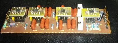
Anyways here is a picture I snapped with my phone of the circuit.
So I got around to not only looking through the other components, but also building a prototype of the circuit. Amazingly enough it works. I was honestly expecting to let the magic smoke out of at least a couple components given this was my first circuit to ever deal with Op-Amps.
Since I didn't have the oscilloscope nearby at the time, I opted to just run some sine waves through, and amp it to a spare speaker. Very unscientific but it still proved that the circuit worked as intended. I need to order in some different opamps to experiment with; at the time I only had a pile of SSOP package JRC 4580's (the nice op amps are currently MIA at the hackerspace). Needless to say making and soldering those breakouts for the tiny SSOP packages was quite a chore. Normally not worth it for such a cheap IC, but with nothing else readily available I did what I could to get the circuit to where I could play with it. At the very least I now know I can solder SSOP packages.
As far as other components go, I found the necessary parts to alter the boards for the following frequencies using 1% caps and 1% resistors: (I also misread some of the parts I already had, and now that I have better lighting I can properly read the color code)
275, 305, 350, 416, 437, 504 and
2750, 3050, 3500, 4160, 4370, 5040 Hz
Needless to say I think I am just about covered for most any application I want. Honestly I was happy with the 305/3050, 350/3500, and 416/4160 as it encompasses most anything I could personally want from an active crossover, but I suppose there is always room to tune it a bit for each speaker it is ultimately paired with.
Anyways here is a picture I snapped with my phone of the circuit.
Attachments
Last edited:
- Status
- This old topic is closed. If you want to reopen this topic, contact a moderator using the "Report Post" button.