Hi.
I'm repairing a AMEK mixing board but i dont have an extensor to power the channel's that i'm fixing.
What i'm doing is comparing some readings on a good channel with the bad channel.
The EQ section of the board as 4 TL074CN IC's, and some are busted, but i dont have a way to see wich are ok and wich are busted because i cant power the circuit.
So i need to do some kind of circuit to test the IC's.
The TL074 brochure has a audio amp circuit (fig.25) wich i can try to replicate, but i have some questions.
Using a DC power supply, should i feed 12V to CC+ and hook up the ground to CC- and feed 6V to ground?
Thnks
See this schematic. I use an 18VDC car race wall transformer, and 2 each 1n5344 8v zeners to make +-8v, with the middle of the two zeners the signal ground. I used 22 ohm resistors since the zeners are 5 W rating. If you have a supply with 0, 6, and 12 you could try that but the performance at +-6v doesn't give you much headroom. In that case the 6v point would be the signal ground, you could call the 0 point the -6 v supply. Corners of the 8 pin DIP IC are plus (pin 8) and - (pin 4) voltage.
Attachments
Obviously your op amps have more than 8 pins then. Go with your datasheet, I'm not going to download a TL074 datasheet. Filter caps can be between 220 uf and 3300 uf, 16 v rated or above, whatever you have laying around. Don't forget to also put .01uf to .47 uf ceramic disk caps between the power supplies and signal grounds near the op amp socket (to prevent oscillation). The plus of the filter caps goes towards the plus of the wall transformer, but if you are not familiar with zener diodes, the line end goes to the resistor connected to the plus of the DC producing transformer. ( When you use regular diodes as rectifiers, the other end goes to the transformer and the line becomes the plus out. If you can only find an AC wall transformer, you would use a rectifier like 1n4007 to the transformer, followed by another electrolytic filter cap to make the 18 VDC).
Last edited:
Its very rare for an opamp to fail unless there has been a problem with its power supply.
That said, if you really believe these opamps have failed then they cost peanuts to replace")
Before you do that though, do make sure that their power supplies are OK.
A basic test of the opamp can be done in situ by measuring carefully the DC voltages on the two input pins (per opamp) and its output pin. If one input is higher or lower than the other then the output pin will appear to be stuck high or low too. And that could indicate some external component problem.
Failed opamps come way down the list of suspects and if one (or more) has really popped then there will be some contributing factor.
That said, if you really believe these opamps have failed then they cost peanuts to replace
Before you do that though, do make sure that their power supplies are OK.
A basic test of the opamp can be done in situ by measuring carefully the DC voltages on the two input pins (per opamp) and its output pin. If one input is higher or lower than the other then the output pin will appear to be stuck high or low too. And that could indicate some external component problem.
Failed opamps come way down the list of suspects and if one (or more) has really popped then there will be some contributing factor.
Hi guys.
Thanks for the help.
So i changed all the opamps and the problem remains, so it's not a IC thing.
I don't have a way to power the circuit to measure the DC of the two inputs....
What kind of test's can i do on a unpowered circuit (comparing it to a good one) to find a busted component?
Thanks for the help.
So i changed all the opamps and the problem remains, so it's not a IC thing.
I don't have a way to power the circuit to measure the DC of the two inputs....
What kind of test's can i do on a unpowered circuit (comparing it to a good one) to find a busted component?
I suspected as much re the opamps.
Unfortunately comparsion rarely works unless you stumble across an obvious issue such as a short or open circuit.
You need to power this up and do basic voltage tests at the very least. Voltages you can compare one channel to another and that stands a good chance of revealing the problem.
Maybe if you posted some clear pictures of the PCB top and bottom then that (might) help.
Hi guys, thanks for the help.
I can power up the mixing board. It's a large studio AMEK mixing board with an external power suply unit.
The channels are detachable from the board, i have to take them out to look (or measure) the components.
Normally this type of desk comes with and extension cord, so that you can power the Ch. of the board and do maintenance, but i dont have one.
I'm doing resistance test and voltage drop test (diode test).
I managed to find a diode that was 200mv off, i changed it but the Equalization section of that ch still does not work.
I'm posting a picture of the EQ. section.
I'm shure the problem is in the eq section cuz I changed this section with one from another Ch, the problem migrated (the ch that was working OK stoped having eq, the ch that had the eq busted started to work properly)
Thanks for the help
An externally hosted image should be here but it was not working when we last tested it.
Add your pictures to the site,
Too add a photo.
First click "go advanced" in the box below the "quick reply" message box. Doesn't matter if you decide half way through a message to do that, it carries it foward.
Then click "Manage attachements". Maximise the new Window so that you can see all the text.
Click browse in the first box at the top and find your picture. Repeat for any more pictures.
Click upload... a message appears "uploading"
When complete the files will show as being attached. Now click the small text that says "close this window"
The pictures should now be attached and when you submit your post they will appear.
Make sure your pics aren't too big, a couple of 100k is plenty, and many members object when they are massive and it alters the margins
It tells you in the attachments window what max sizes are allowed.
If you want to attach a file that has a non standard format for example excel, circuit simulation etc then try putting the files in a zipped folder and attaching that.
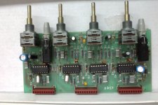
That doesn't look to scary
Its always nice to fault find properly by measurement but just looking at the PCB the stand out and perhaps more obscure failure items would be the two tantalum capacitors and the ceramic caps. Other things to check first though.
The two blue electroylitic caps look as though they could be rail decoupling. Try and confirm if they go to the power pins of the IC's. There are two ? diodes at the right hand side next to one of these caps. Always worth a check as they are a typical failure item. There are a handful of small signal diodes scattered around. Again always worth a check for leakage. Without a circuit I wouldn't like to say what these do. They could be related to the PSU or some on/off thump suppression. You would have to check them out of circuit (just lift one end) for leakage.
The resistors and the poly caps almost certainly OK. That just leaves physical damage such as a broken track.
If you can determine the PSU connections then powering this up with two 9 volt batteries is a real possibility and would allow you to compare the good and bad PCB's.
I'm assuming it does run on dual (split) supplies going of the two blue electros but you need to be sure. See where the IC power pins go.
R1 looks a bit discolored.
Also, I don't think I ever run across caps that look like those, eg C17, C7, C14. They look like SMT with radial leads added on.
They are polyester film box capacitors
Hey guys.
I fixed the problem, it was one of the polyester capacitors "C17, C7, C14..."
Cheers for the help.
Just one quick question, when you guys need to check a cap, do you cut one of the legs from the board or do you unsolder them?
I measure them with a analog multimeter, is it a full proof test?
thanks!
I fixed the problem, it was one of the polyester capacitors "C17, C7, C14..."
Cheers for the help.
Just one quick question, when you guys need to check a cap, do you cut one of the legs from the board or do you unsolder them?
I measure them with a analog multimeter, is it a full proof test?
thanks!
That's great you have fixed it. Well done
I'm really surprised it was a polycap that was duff but yes, testing on an analogue meter on a high ohms range usually shows leakage particularly if its like an old AVO that uses a 15 volt battery. I would always just try and desolder one end with braid providing that's possible... single sided PCB, component legs not twisted and embeded in the PCB etc. No test with any meter can determine fully if the cap is good though, although most cap problems on non electros are leakage related.
I'm really surprised it was a polycap that was duff but yes, testing on an analogue meter on a high ohms range usually shows leakage particularly if its like an old AVO that uses a 15 volt battery. I would always just try and desolder one end with braid providing that's possible... single sided PCB, component legs not twisted and embeded in the PCB etc. No test with any meter can determine fully if the cap is good though, although most cap problems on non electros are leakage related.
- Status
- This old topic is closed. If you want to reopen this topic, contact a moderator using the "Report Post" button.
- Home
- Source & Line
- Analog Line Level
- Test IC TL074 CN