Hello,
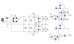
I'm working on an opamp based preamplifier. I'm very new to this so if someone could check it over and see if there are any mistakes/improvements that could be made.
Also I have a few specific questions:
1. What value should C107 & C207 be to provide RF suppression?
2. Should I also use capacitors soldered directly to the RCA inputs for RF? I've seen this mentioned a few times. If so, what value?
3. Is the gain switch (S101 - 201) likely to cause any problems (pop or thumps)?
4. Would a 5VA transformer be sufficient?
Thanks in advance
Attachments
I would double the HF roll-off frequency compared to the Power Amplifier.
If your Power Amp has 1us then use ~0.5uS at the pre-amp input, i.e. 1k0 & 500pF, (470opF would suit).
But if you have set your Power Amp to 0.33us then C~150 or 180pF at the Pre input.
Similarly I recommend that the LF bandwidth also be doubled relative to the Power Amp.
If you are using a 18+18Vac for a +-18Vdc regulated supply then a 5VA gives ~ 69+69mAdc maximum continuous at the regulator. Assume the reg uses 5mA then that leaves plenty for two channels drawing 10+10mA each. i.e. continuous draw is ~36% of maximum.
However, you may find that a larger transformer with a CRC PSU before the regulators performs better.
Last edited:
For optimum low distortion that op-amp should be fed from a source that is less than 2k. Ohms, if greater then the source resistance should be the two feed back resistors in parallel, having the volume pot at the input also puts the top part of the pot's thermal noise directly in series with the signal
It is much better to split the gain between two op-amps.
In this the first is connected directly to the signal source it will usually see less than 2k. source resistance, this optimizes distortion performance and reduces thermal noise.
Putting the volume control between them enables you to use the linear pot shunted with a resistor method to achieve an accurate log law and you can use a much lower pot impedance, I myself prefer the virtual earth scheme using a feedback volume control.
rcw
It depends upon whether you are using a non inverting stage, in this case a 10k. balance pot across both outputs, with the wiper grounded followed by a 100k. pot with a 15k. input resistor to the second op-amp. works well.
If you use a virtual earth then you can use a 10k volume pot around the loop then use a 20k. pot across this as a balance pot. in this you connect the wipers to different ends of the pot to adjust balance.
The last one I built was many years ago and then you could get dual concentric pots and remove the need for a balance control, in this case you can use a 20k. pot and 3k3 resistor for the first scheme.
rcw
- Status
- This old topic is closed. If you want to reopen this topic, contact a moderator using the "Report Post" button.