Let me 'clarify' my personal opinion on making discrete audio gain modules.
As I have, for more than 40 years, I support making discrete circuity, WHEN a real advantage is shown or implied over a quality IC. However, this is not always the case.
For example, when Parasound asked me to build a phono stage ultimately called the JC-3, I was told NOT to use discrete jfets, because we were having such severe supply problems sourcing enough Toshiba jfets for the rest of our products. At that point, I reluctantly decided to use quality IC's and hope for the best.
Of course, I could have just gone back to bipolar transistors everywhere, like I started with in 1967, and still have a reasonable topology, but what is the point? Space and other considerations also limited my choices, initially.
Now, what did I find? First, IC's CAN be very quiet, almost as good as massed pairs of jfets. IC's are pre-trimmed at the factory for extremely low voltage offset, so SERVOS are not always necessary. It is almost IMPOSSIBLE to get similar performance without monolithic pairs of active parts, and they are getting hard to get.
Back 40 years ago, when I had to replace an IC that I found, with discrete, the best slew rate, low noise, and +/- 24V operation IC that I could find at the time, the HA911, only had a slew rate of 2.5V/us. Today, 20V/us is typical, thank goodness for progress. At the same time, the input noise dropped about 10 times from the early days.
When I started to make discrete modules for the GD, and ultimately, Mark Levinson, the jfets that are sometimes discussed here, like the j113 and the j175, were newly introduced. Siliconix also made another part, the J110 that truly could do about 1nV/rt Hz at 1KHz or so. The bipolar transistor with the lowest voltage noise at the time was the 2N4401, 2N4403 pair. These are modest, medium beta devices, and were not good over a wide range of impedances. At that time, a typical low noise device might have 2-4nV/rt Hz, mostly from extra base resistance.
Only in 1978, did the Japanese introduce improved versions to replace the 2N4401, 2N4403 in many applications.
Unfortunately, even though we went through a 'golden age' of individual and dual bipolars and jfets, for maybe 30 years, that time is over.
Yet, many IC's have improved enough to be viable. I realize that many here think that IC's sounded as good as the best discrete, and the difference is in our imagination, but I have never found it to be so. However, IF you want to build a discrete circuit with parts out of your junk box, you are going to be very disappointed. Better to use IC's, with DUE CARE using the best passive parts surrounding them.
You keep insisting on this: 'losing the servo' but many times the inclusion of a servo allows a better quality audio path to be designed.
perhaps. So far I havent seen anyone come up with a circuit topology that amplifies and is self correcting in dc offset. Why is that? Why isnt it integrated?
I suggested the servo but that was decades ago. I go off and do other things and come back to my beloved hobby and not much has changed in circuitry. Well IC have changed some but even those still have dc servo as an outboard appendange. What's that all about?! -RNM
Last edited:
Except that the resistor will always need be smaller than the one that would substitute for said current source, so there is a penalty, unless you can make the voltages in the circuit appropriately larger.
True, but you get back higher gain in the first stage and ultimately lower, or at least not higher, input referred noise.
jan
What's currently the "best" FET input monolythic opamp, if an external output buffer (class A, yada yada) is assumed?
AD744 with a discrete diamond buffer driven from pin 5 is worth a try.
What's currently the "best" FET input monolythic opamp, if an external output buffer (class A, yada yada) is assumed?
OPA827
ADA4627
The whole opamp can be heated by precisionally controlled heater, to keep it's temperature stable.
I guess you could put a vacuum tube right next to it.
")
Thanks Jan! Yes, I fished through email and found that it was On Semi that I'd seen first, although the link to the Electronic Products issue has long expired. And I remember that bit about the Sanyo on-chip 220mohm resistors that tended to blow up
EDIT: I also remembered the suggested circuits, which I immediately wanted to do differently
A cool thing (npi) would be to infrared-image the die and use that information. Certainly could be fast response
Brad
It is highly unstable with the output cascode, but quite easy to tame without.
If I remember well it must work at very high closed loop gain to be stable; moreover its output impedance is fairly high, and both its gain and freq response are strongly affected by loading - nice topology, but imho is pretty useless as a line stage unless some isolation of the gain node is provided by an output buffer, or the output cascodes are operated at a much higher quiescent current.
L.
Last edited:

Sorry everyone. Post #391 was a glitch.
The IR detectors were dropped in here specifically due to the IR image of a die they can provide. See here:
You can’t realistically have 2/10 d. Celcius resolution temp. mapping of a surface divided into 25x25um areas and following the dynamic variations of the temp at ~1kHz of all these “pixels” with other methods.
All this at a very reasonable price and minimum complexity for a manufacturer or researcher.
But still very expensive for the hobbyist. (That’s why the talking turned to the IR spot thermometer).
This rule of thumb is the basic equation of thermography :
"Emissivity + Reflectivity = 1"
You want to maximize emissivity for to have correct IR temp. measurement. You have to minimize reflectivity to achieve this (shiny aluminum is very reflective).
A trick to achieve a spot with max. emissivity (~1 ) on any material, is to drill a blind hole on it with a depth > 2-3d.
IR temp. measurement into this spot is really very close to the true local temperature.
Brad, it sounds to me (especially the counter-effect cooling had on the intensity of the emission) as if it was actually IR emission not adequately filtered in front of the CCD.
Did they verify the wavelength?
Wavebourn
Raising the temp of the whole opamp, will worsen the dynamic temp. unbalance.
A specific subcomponent when variably heated due to it’s I*R will find it more difficult to get rid of it’s thermal energy through the hotter surrounding mass.
The delta temp. with another subcomponent (less I*R loaded) will thus increase.
George
Not being an expert in electronic applications at all I am wondering why a simple thermocouple device could not be used for checking temperature rise? I used these all the time in manufacturing in autoclave applications and also in temperature control circuits. Perhaps the rise time is just to slow to tell you what you are looking for, but it would seem to be more specific than a simple IR handheld device. How could you narrow the specific heat source with one of those devices? You would pick up all the surrounding heat sources and I have never seen a handheld IR that had that narrow of a field of view?
The IR detectors were dropped in here specifically due to the IR image of a die they can provide. See here:
A cool thing (npi) would be to infrared-image the die and use that information. Certainly could be fast response
Brad
You can’t realistically have 2/10 d. Celcius resolution temp. mapping of a surface divided into 25x25um areas and following the dynamic variations of the temp at ~1kHz of all these “pixels” with other methods.
All this at a very reasonable price and minimum complexity for a manufacturer or researcher.
But still very expensive for the hobbyist. (That’s why the talking turned to the IR spot thermometer).
Yes, emissivity is clearly important to take into account (I'm reminded of the rule-of-thumb at aluminum extrusion houses: assume any piece of extrusion is very hot until proven otherwise, as the emissivity of bare Al is so low!).
This rule of thumb is the basic equation of thermography
:"Emissivity + Reflectivity = 1"
You want to maximize emissivity for to have correct IR temp. measurement. You have to minimize reflectivity to achieve this (shiny aluminum is very reflective).
A trick to achieve a spot with max. emissivity (~1 ) on any material, is to drill a blind hole on it with a depth > 2-3d.
IR temp. measurement into this spot is really very close to the true local temperature.
Another confounding variable for looking at a transistor with a short-wavelength detector: they are, to varying degrees, light emitters! In high-field regions especially. When Janesik et al. were developing CCDs for astronomy, there was a persistent excess of apparent dark current in the vicinity of the on-chip output amplifier. It turned out it was light emission from the MOS part, and iirc it got a good deal worse with cooling. They had to turn the amplifier off during long exposures.
Brad
Brad, it sounds to me (especially the counter-effect cooling had on the intensity of the emission) as if it was actually IR emission not adequately filtered in front of the CCD.
Did they verify the wavelength?
The whole opamp can be heated by precisionally controlled heater, to keep it's temperature stable.
Wavebourn
Raising the temp of the whole opamp, will worsen the dynamic temp. unbalance.
A specific subcomponent when variably heated due to it’s I*R will find it more difficult to get rid of it’s thermal energy through the hotter surrounding mass.
The delta temp. with another subcomponent (less I*R loaded) will thus increase.
George
Well, there are always Peltier elements available... How cold do you want it?
gpapag,
Thank you for the explanations George. I actually follow this quite well except my math is more than rusty... I am glad you pointed out the fallacy of increasing the temperature to control temperature as this just seemed completely incorrect to me. By doing that you have just shot yourself in the foot by what appears to be decreasing your chances of dissipating the rising die temperature to a lower stable temperature. Wouldn't you be better off using a direct contact heat exchanger, a finned heat sink than using air as the direct transfer function? I only suggested the thermocouple as they are so cheap and attached directly to the die with a simple hand held meter you would have a very instantaneous reading of temperature rise. You could also drill a hole as you stated and insert the thermocouple into that hole. I had not seen a hand held with that resolution of depth of field. By drilling the hole you would appear to have two affects, one being the properties of the cavity depth to width and the second being a much thinner substrate that has a time lag in response to the actual temperature change internal to the device. Am I following what you are saying properly? Thanks again.
Steven
Raising the temp of the whole opamp, will worsen the dynamic temp. unbalance.
A specific subcomponent when variably heated due to it’s I*R will find it more difficult to get rid of it’s thermal energy through the hotter surrounding mass.
The delta temp. with another subcomponent (less I*R loaded) will thus increase.
George
Actually, that is not the case.***
Interchip dynamics will not change unless the gradient to the outside world is different for each chip. If for example, one die's heat must go past the other to get out.
***the astericks are because the thermal conductivity of silicon is temperature dependent, the eq is:
Kt =286/(T -100) for T =300 to 600K
Cheers, jn
First off this is for fun and exchanging some ideas. I make no claim to inventing anything here it has all been somewhere before.
Classic op-amps input gm, Vas, and output buffer all end up relying on a linear input voltage to current stage (gm) feeding current to a high impedance node whose voltage is buffered to create a low output impedance. There are lots of embellishments around to increase the DC gain but the AC performance is usually limited by the linearity of the gm, the linearity of the gain node impedance (at AC frequencies the compensation capacitance plus any parasitics), and both the current needed to drive the output buffer and the voltage error across the output buffer. The last is problematic in that it (usually the crossover distortion) is differentiated before it can be expressed as an input current error, hence the rapid increase as frequency increases.
Before I go on I would like to say that a one size fits all op-amp is simply an unnecessary restriction. A simple enough signal path can give the user a couple of foolproof component substitutions that can optimize it for each application.
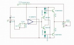
This being said I want to present a very ordinary signal path with a couple of additions to preserve simplicity and linearity. This circuit is not new but there are some differences to previous versions that I have seen (I don’t see everything posted). The signal path on the non-inverting side has been arranged more like a current mirror and on the other a folded cascade. The cascodes on the gain stage have their base current recaptured to keep the collector impedance very high and eliminate non-linear capacitive currents. The bootstrapped triple darling presents a very light load to the gain node and can be independently customized to easily drive low impedances. Though as I have previously stated there is no reason for every op-amp in your signal path to drive something like 50 Ohms.
The circuit here is just an outline and the devices are place holders but even with these fairly ordinary devices Aol is > 100k and more importantly the gain at 20K is 75dB. J1 and J2’s currents are set for bias and to set up the lower half of the input stage to also recapture the base current of the cascodes. Originally I had planned on a completely symmetric circuit with PFET’s. That is a fairly easy exercise for the reader.
I would like some suggestions for transistors, as far as I can tell I can get better than -100dB distortions at 20K, etc. with nothing more than this. As I said the degeneration resistors and comp cap would need to be changed for gain of one operation.
Hi Scott
I agree with everything you are saying here.
I think your circuit is the most interesting here so far.
I'll put it in to my simulator and have a closer look at it.
BTW: is this the model you are using for the BF862?
* BF862 SPICE MODEL MARCH 2007 NXP SEMICONDUCTORS
* ENVELOPE SOT23
* JBF862: 1, Drain, 2,Gate, 3,Source
Ld 1 4 L= 1.1nH
Ls 3 6 L= 1.25nH
Lg 2 5 L= 0.78nH
Rg 5 7 R= 0.535 Ohm
Cds 1 3 C= 0.0001pF
Cgs 2 3 C= 1.05pF
Cgd 1 2 C= 0.201pF
Co 4 6 C= 0.35092pF
JBF862 model parameters:
.model JBF862 NJF(Beta=47.800E-3 Betatce=-.5 Rd=.8 Rs=7.5000 Lambda=37.300E-3 Vto=-.57093
+ Vtotc=-2.0000E-3 Is=424.60E-12 Isr=2.995p N=1 Nr=2 Xti=3 Alpha=-1.0000E-3
+ Vk=59.97 Cgd=7.4002E-12 M=.6015 Pb=.5 Fc=.5 Cgs=8.2890E-12 Kf=87.5E-18
+ Af=1)
ENDS BF862
Cheers
Stein
Yes, in fact I believe that was one of my and Vogel's points in our LTEs.True, but you get back higher gain in the first stage and ultimately lower, or at least not higher, input referred noise.
jan
If I remember well it must work at very high closed loop gain to be stable; moreover its output impedance is fairly high, and both its gain and freq response are strongly affected by loading - nice topology, but imho is pretty useless as a line stage unless some isolation of the gain node is provided by an output buffer, or the output cascodes are operated at a much higher quiescent current.
L.
Agree. I wouldn't be so enthusiastic about losing the cascodes, as besides higher unloaded gain they reduce the effect of thermals in the preceding stages. But a buffer is a good idea, then the compensation required won't be so load-dependent. Of course this is basic stuff.
- Home
- Source & Line
- Analog Line Level
- Discrete Opamp Open Design