The 22K to ground was a nod to those that think 20KHz open-loop BW improves things, what I'm not sure. This should probably be left for listening experiments.
Those interested should also see Putzeys' article in Linear Audio for his take on having more gain at lower frequencies, and its effect on settling time.
It would be interesting to add overload behavior to the repertoire of tests in sim and in reality, including behavior under excessively high slew rate signals.
Virtually all conventional feedback amps (single-ended ones) will overload asymmetrically, the cure for which is making them faster, or bandlimiting ahead. Of course really poor slewing performance may require a lot of bandlimiting! But such performance is easy to avoid. According to Zanfino, Miller determined that Otala selected particularly poor designs to support his arguments about TIM. This does not invalidate the thesis, but it exaggerates a bit.
Once you make the bandwidth flat out to the highest frequencies of interest, does this guarantee equal distortion performance at all in-band signals? No, as there are other mechanisms besides those that the loop gain alleviates. One of the things I like about what linuxguru posts is the inclusion of the 1k resistor in series with the source, which is a reasonable start for what may be feeding the amplifiers. Those who omit any consideration of the source impedance are inviting sweet Spice lies.
Those interested should also see Putzeys' article in Linear Audio for his take on having more gain at lower frequencies, and its effect on settling time.
You know, it depends. This example has no GNFB, and THD below 0.0005% in audioband. I suppose no one would also predict TIM problems
")
Attachments
When I said conventional feedback amps, I meant conventional feedback amps with global feedback.You know, it depends. This example has no GNFB, and THD below 0.0005% in audioband. I suppose no one would also predict TIM problems
Those interested should also see Putzeys' article in Linear Audio for his take on having more gain at lower frequencies, and its effect on settling time.
Putzeys, in a later discussion in the John Curl thread here in DIYAudio, also made the point that the transfer function of the fedback signal differs above and below the open loop pole. Above has additional phase shift, of course, but this is a different transfer function.
Does this matter? And is it even possible to generalize? Dunno.
Thanks,
Chris
Aren't those p-channel FET's?
Thanks,
Chris
Yes, sorry PFET's were the only thing compatible so it's one flavor of each device.
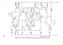
Wilson opamp
Hope these don't get Wiley's panties in a bunch, as they say. If so I'll take them down.
The spine is a little the worse for wear, but I've gotten a lot of use out of this book.
Hope these don't get Wiley's panties in a bunch, as they say. If so I'll take them down.
The spine is a little the worse for wear, but I've gotten a lot of use out of this book.
Attachments
Settling time of GNFB design depends on frequency compensation method used.
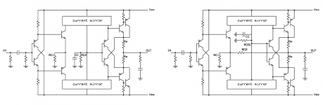
Also, depends -- if CMF circuit - no Cdom.
Also, depends -- if CMF circuit - no Cdom.
Most of the circuits I've seen have ample junction capacitance to act as such.
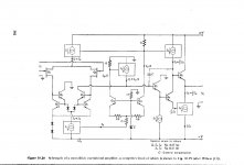
Dick you would like the Wilson current mirror Wiki page. Barrie Gilbert and George had an overnight bet on who could make the best current mirror out of only three transistors, and George won.
I find it strange since given the first two there are not many ways to connect a third.
Last edited:
Those interested should also see Putzeys' article in Linear Audio for his take on having more gain at lower frequencies, and its effect on settling time..
Bruno Putzeys lives here.
jan
Such an excellent article! As you remarked, the core material has appeared elsewhere, but Bruno's exposition is masterful. And note that he also listens (see for example the remarks about high-frequency loop gain deficiencies in the third paragraph on page 13).
Good article (quite basic findings, though) , but some of the statements are at least controversial, like: "Open-loop bandwidth is no measure of how fast an amplifier is. Gain-bandwidth product is"
GBW speaks only about small signal "speed".
Instead of Wilson Type, the third could be used as "helper" to overcome the base current difference?Most of the circuits I've seen have ample junction capacitance to act as such.
Dick you would like the Wilson current mirror Wiki page. Barrie Gilbert and George had an overnight bet on who could make the best current mirror out of only three transistors, and George won.
I find it strange since given the first two there are not many ways to connect a third.
Here is a good book by the late Hans Camenzind, check Page 3-4 to 3-6 for these mirrors.
He died past August 8th, RIP Hans.
Last edited:
One of the strength of his article is, that if you skip the math, the narrative and graphs still make the issues - and misconceptions! - very clear.
Even if there can be some counter-arguments to some of his reasoning, it beats the tired 'everybody knows....' mantras.
jan
Even if there can be some counter-arguments to some of his reasoning, it beats the tired 'everybody knows....' mantras.
jan
Good article (quite basic findings, though) , but some of the statements are at least controversial, like: "Open-loop bandwidth is no measure of how fast an amplifier is. Gain-bandwidth product is"
GBW speaks only about small signal "speed".
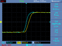
I believe you should not pull this out of context. He reasons, and shows graphs, comparing rising waveforms from the two extreme positions and then concludes what he said.
I don't think you can argue with that reasoning and thus the conclusion from that reasoning.
BTW Bruno will come to Burning Amp this year so you can tell your objections to the man himself ;-)
jan
Many thanks to Jan for making this article freely readable
Doing some tests on what Bruno writes about in his article was more or less my idea when I started playing with discrete CFAs.
L.
Attachments
Nice to see that article again ...
Frank
The simple phenomenon that's occurring here, is that better performance in one part of the overall system, audio, that is, then emphasises weaknesses elsewhere, shines the spotlight more strongly on the remaining deficiencies. So, there are two obvious choices here: clean up the remaining deficiences, or lower the strength of the spotlight and mask, soften the edges of that "unpleasant stuff". Reducing feedback is an easy version of the latter appoach; it seems only a few appear to take the other tack, and with gritted teeth push through to the logical conclusion - eliminate all the subjectively audible distortions. But they're the ones who reap the ultimate rewards ...Only in audio does the usefulness of feedback draw heated debate, with detractors saying that reasonably good measured performance obtained without feedback sounds better than excellent performance obtained with feedback.
Frank
I don't think so, fas42. Reducing feedback also reduces potential distortions that are MORE exotic than we can easily measure.
I am pleasantly surprised that Richard Marsh brought out the high open loop bandwidth. He apparently is not aware of the prejudice against this concept shown on this website in the past. However, I agree with him, that it is useful and important to have high open loop bandwidth.
I am pleasantly surprised that Richard Marsh brought out the high open loop bandwidth. He apparently is not aware of the prejudice against this concept shown on this website in the past. However, I agree with him, that it is useful and important to have high open loop bandwidth.
Reducing feedback also reduces potential distortions that are MORE exotic than we can easily measure.
Reducing something that might be there but we can't see?
I don't think so, fas42. Reducing feedback also reduces potential distortions that are MORE exotic than we can easily measure.
May be this is one of the potential distortion mechanisms you are addressing:
(P.364 from the excellent book of Bob Cordell: Designing Audio Power Amplifiers )Negative feedback can exacerbate undesirable clipping behavior. When clipping occurs, the error signal at the input of the amplifier becomes very large and may overload one or more stages of the amplifier. Those stages, having been overdriven, will take time to recover and get back to their proper signal voltages after the input is no longer being overdriven. The VAS is especially likely to become overloaded. Delays introduced by frequency compensation capacitors may lengthen the time required for recovery. It is especially important that output transistors not be allowed to saturate.
Negative feedback sharpens up the clipping edges. This happens largely because the gain from input to output at the onset of clipping attempts to go from the closed-loop gain to the open-loop gain. This happens because there is no global negative feedback once the amplifier clips.
This may look exotic to me that I am an - non EE - amateur, but for a cautious designer, it should be a more homeland one.
Short time clipping certainly has the potential to occur in listening sessions quite frequently and get unnoticed.
The acoustic signature of clipping and subsequent sticking will be attributed to increased feedback from a person that adjusts the amount of feedback on an amplifier he is building/optimising and then evaluating by listening to music.
It is difficult to spot short term clipping while measuring, as the source material is rarely a music piece. The crest factor on some music is high and we may underestimate the overhead actually required.
Therefore, it is even more difficult to locate the stage that distorts first, then think of the underlying mechanism and decide on the remedy.
Regards
George
Last edited:
- Home
- Source & Line
- Analog Line Level
- Discrete Opamp Open Design