This completely changed the noise picture, and obsoletes the discussion here, as what is being discussed at the moment is an almost 50 year old observation, and rather simplistic as well.
I some sense the disscussion is eternal, the simple basic physics. Why do you put down the folks that are not facile in every detail of the basics?
Mr. Marsh, what current did you measure this at?an 2SA1316 is 'typically' 0.6nv/rtHz and measures 1.2nv. More creative specmanship?
My own measurements of rbb' show Motorola 2sa108x 2sc254x about 5r1
But the noise contours on the datasheets suggest rbb' > 10r ... as do the datasheets for Toshiba 2sc3329 2sa1316.
I want to make unbalance microphone pre-amp using discrete op-amp. THD is not very importance. I can accept 0,01% THD at 1kHz 1Vrms. But I want input noise voltage as low as 1nV/vHz. Is that possible?
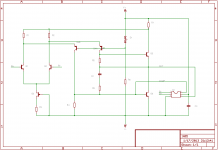
It's within reach, and the discrete-opamp topology (Kaneda-like topology with folded PNP cascode) shown below probably gets close to the voltage noise requirement and surpasses the THD requirement - ~-90dBr 2nd harmonic as a unity-gain buffer at 1Vrms, THD20. It doesn't have performance specs that are comparable to some of the other high-performance discretes in this thread, but it uses Class-A biasing, which helps it sound very detailed and non-fatiguing in typical line-level or lower applications.
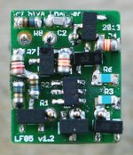
The prototype shown uses Toshiba 2sc3324-BL for all NPNs, and micro-MELFs at all key locations in the signal path (a couple of constant-current bias resistors are thick-film SMD).
I've never tried it as a microphone preamp, but if you can tolerate an input bias current of about 2.5 uA (LTP tail current is ~ 2 mA, LTP DC beta about 400 each), it should work OK as a preamp at rails as low as +/- 3V (the sweet spot is about +/- 9..15V, and max rail voltage is about +/- 20V). There's also a fair amount of input DC offset in this topology due to mismatched LTP Icq. GBW runs to about 10 MHz in the prototype, which can be raised to 20..30 MHz if there's no requirement for unity-gain stability.
Attachments
…
Then you have to add the Rbb'. For about 10 years, the 2n4403 with an Rbb' of perhaps 30 ohms, was the device to use for moving coil cartridges, but then in 1978, the Japanese made a number of superior devices that had low Rbb' as low as 2 ohms.
…
Hi John,
What are those Japanese devices?
Probably the famous Rohm 2sb737/2sd786, or the even better (and later) Toshiba 2sc3329. There are also the Hitachi 2sc2545/6/7, NEC 2sc1845/2sa992 and Toshiba 2sc2240/2sa970.
The best SMD ones in general availability today are probably Toshiba 2sc3324/2sa1312 and 2sc4117/2sa1587, though they're probably not quite as good as the through-hole Rohm pair.
The best SMD ones in general availability today are probably Toshiba 2sc3324/2sa1312 and 2sc4117/2sa1587, though they're probably not quite as good as the through-hole Rohm pair.
Mr. Marsh, what current did you measure this at?
My own measurements of rbb' show Motorola 2sa108x 2sc254x about 5r1
But the noise contours on the datasheets suggest rbb' > 10r ... as do the datasheets for Toshiba 2sc3329 2sa1316.
I find the 2nV at 10Hz a little hard to believe for a 2N2219 but not impossible, a quick experiment put 50 Ohms in the base you can calculate exactly where the noise should go to, I don't think there is enough Ib to matter in 50 Ohms.
I'm sorry, I did not mean to constrict the flow about practical transistor use. I just happen to have worked with the 2N2219, 45 years ago, and I know it pretty well. It was originally designed as a magnetic core driver for main frame computers, and that is why it has such high rated current
(800ma), so it is optimized for another application, other than typical audio designs. We did use it more than 45 years ago for audio, but only for relatively low voltage operation. It does have a complement (2N2905) and it was one of the few common complementary pairs available at the time. So as an output stage, there were somewhat better devices that worked better as a VAS or complementary output stage due to improved linearity or voltage breakdown of the other devices.
As far as an input is concerned, it is fairly quiet (as recently discussed) but not the best candidate, even of common, easy to get parts. The 2N4401/3 complementary pair is actually better for low Rbb', and why we used them 40 years ago in the Levinson JC-1, instead of the 2N2219.
The other problem is the beta droop that happens more with this device than many others that are designed for low noise operation. Apparently designing for high peak current compromised the beta for operation at 1ma and below, and this is very important for an input that does not get noisy with more than 100 ohm drive impedance, do to the contribution of the current noise that is inversely proportion to beta. So while this part has been very popular over the decades for less critical stuff, it is not very optimum for an input, midstage or output part, due to its tradeoffs, made initially in designing the device. I hope this helps, and I hope that I do not sound too judgmental, like I apparently did in my earlier input.
No John ")
These old RCA devices available by central semi, not sure about stocking, 2n3439 and the 2n5415
Looks like ST has dropped them too, probably because of the expensive TO-39 can.
I would think that ksc3502/ksa1381 or others in the TO-126 case would be good subs. Onsemi is offering Sanyo parts too.
Transistors Bipolar - BJT | Mouser
Thanks John, but what about a second stage complementary push pull cascode with + and - 90v rails in a power amp. You need good high voltage transistors and not many have been made since RCA/Motorola made the 2n3439 and the 2n5415. I know there must be some more modern transistors than mid 60s devices. Haven't they improved the process with less impurities? Ray
The 2N3439/5415 are very, very slow in modern terms and Hfe is weakly defined. Today we have the 2SC4793/A1837 which have already been popular for many years. The Sanyos available through OnSemi may be even nicer. The MJE340/350 would also work, though they aren't as fast.
Is there something that makes these transistors not very good? It seems to me there are plenty of possibilities.
Is there something that makes these transistors not very good? It seems to me there are plenty of possibilities.
Old one's are still good to use.
Oh.
Uh the current, IIRC was 1mA. Using the Quan-Tech as shown in action. Settings are on the meters and switches. Click on the picture and then magnify it. [No series R to the base.]
And, the 2N2219 is Not the other one I tested... it was a 2N2219A. The A is better and with new processing equipment of today, it is better than ever.
The 2N2219A and the 2N2905A are both still in the running for some uses. They are very linear on a curve tracer and in use.
THx-RNMarsh
Last edited:
Note for only the 10Hz it is on the X3 multiplier.... a reading of 1nv = 3nV.
I doubled checked the 'low noise' transistor [BC560C] measures 1.6nV at and above 1Khz. At 100Hz = 2.5nV and at 10Hz is 3 nV
Seems like a good number. I'll go test some other low noise transistors.
THx-RNMarsh
I doubled checked the 'low noise' transistor [BC560C] measures 1.6nV at and above 1Khz. At 100Hz = 2.5nV and at 10Hz is 3 nV
Seems like a good number. I'll go test some other low noise transistors.
THx-RNMarsh
Last edited:
JC, is your recommendation of PE8050-8550 for MC low noise based on experience?I did not recognize those parts, so I would default to the 2N4401/3 pair for general stuff, and the PE8050-8550 for MC low noise.
2n4401/3 has known low rbb' and you can sorta see this from the datasheet though it is not spec'd as a LN device .. eg Vce at high Ib
But PE8050-8550 doesn't seem to show this type of behaviour.
If it is from experience, what do you estimate rbb' to be on PE8050-8550?
Maybe I'm looking at the wrong maker's datasheet.
Last edited:
Mr. Marsh, are these 1mA measurements?I doubled checked the 'low noise' transistor [BC560C] measures 1.6nV at and above 1Khz. At 100Hz = 2.5nV and at 10Hz is 3 nV
As JC points out in #3100, a 'perfect' transistor at 1mA has Rnv = 13R and will have voltage noise of 0.47nV/rtHz
By looking at the real voltage noise at various currents (ie the Noise Contours) you can get a very good estimate of rbb' .. at least for predicting noise. This is a good model for noise at audio frequencies if there isn't much 1/f LF noise. ie letting rbb' represent how close the BJT is to 'perfection'
The first step is to use the 'correct' value for rbb'.keantoken said:What would it take to replicate these measurements in simulation so that BJT models can be improved?
This is RB in LTspice. I use the following to match datasheet noise plots and my Jurassic measurements.
2n4403 38
2n4401 40
2sc2240 39
2sa970 25
bc550c 167
bc560c 170
If RB is unspecified, RB defaults to 10 which is rather good. Pity you can't buy the default LTspice transistors from Mouser or Digikey
If there isn't much 1/f rise in noise, (which should be the case for a 'Low Noise' device) you are done.
You can also estimate rbb' by looking at Vbe at high Ib but doing it from noise measurements is more accurate for noise estimation .. surprise surprise.
A caveat is that rbb' for HF response is often different from that for audio noise.
I dunno how to model 1/f noise in SPICE
Thanks for those numbers. I wonder where the BC3x7 lie?
Noise isn't modeled in transient simulation in LTSpice. Only in noise analysis. You would have to manually add noise voltage sources which is possible, but difficult. However there are BJT model parameters which model the different noise sources that you would see in the noise simulation.
If there are H-parameter plots in the datasheet, that will allow you to model RF behavior including base resistance much more accurately. Transconductance at RF is one thing that usually can't be modeled accurately because even if datasheets show the Ft curve, they don't show you what happens to the transconductance. It falls with frequency, so you can make circuits stable in simulation that in real life are unstable, even impossible to stabilize.
THAT transistor models actually have two different versions, one for accurate noise simulation and another for accurate RF simulation. I don't know whether this is necessary or not, it could just be a limitation of the simulator the models were designed for, although the creators apparently payed a lot of attention to model quality.
Last edited:
- Home
- Source & Line
- Analog Line Level
- Discrete Opamp Open Design