trimming DC offset with 0805 resistors is for the birds. anyone have a recommendation on the smallest possible (preferably multiturn) SMD trimmer?
Here's what I've found so far:
http://copal-electronics.info/en/00011/00ca2.pdf
Here's what I've found so far:
http://copal-electronics.info/en/00011/00ca2.pdf
OK.
and - I am ready to measure a working SWOPA when ever... . anyone made one yet?
Thx-RNMarsh
-RNM
Richard,
I tried keeping up with that thread with Scott's hybrid op amp design and though it was mostly over my head why couldn't it have been done with larger thru hole devices? I know the path lengths would increase a % over his very compact design but would the thru hole design be that much inferior to the smd design? It seemed in the beginning it was more of a challenge to see what could be done with the absolute minimum of devices.
I tried keeping up with that thread with Scott's hybrid op amp design and though it was mostly over my head why couldn't it have been done with larger thru hole devices? I know the path lengths would increase a % over his very compact design but would the thru hole design be that much inferior to the smd design? It seemed in the beginning it was more of a challenge to see what could be done with the absolute minimum of devices.
No difference of import IMO between smd and TH devices.
yes, that was the challenge and SW did a very practical design which I hope will have excellent performance....
I would put one together if it is a PCB with TH. But some day someone will do the smd pcb and then test it and report on it.... [maybe?]
Thx-Richard
.
yes, that was the challenge and SW did a very practical design which I hope will have excellent performance....
I would put one together if it is a PCB with TH. But some day someone will do the smd pcb and then test it and report on it.... [maybe?]
Thx-Richard
.
Sorry guys no time right now, too many other projects on the go.
Did you ever get one built and tested?
-RNM
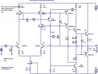
*Bump* - Another set of improvements, this time to the venerable Melcor 1731:
1) Added LTP CCS - many pros and cons, but it reduces THD20.
2) Added LTP Current Mirror - requires some care because of the differential VAS.
3) Added VAS Cascode - tried a lot of arrangements, but ultimately it is deceptively simple. If you look carefully, this is equivalent to the VAS cascode in the SWOPA, but with transistors rather than diodes (one transistor is diode-connected).
4) Re-biased the VAS to keep the VAS currents roughly the same as the LTP currents - this helps to keep the LTP collector loads roughly balanced.
Overall, it is more complex than the FET990, and does not reach the same level of simulated performance or sonics, but it uses mostly BJTs (can be made 100% BJT by using a BJT doublet for the LTP CCS). Four pairs of these can be implemented with (matched) BJT duals.
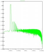
Simulated THD20 at 4V into 600R is a very respectable -130 dBr. It does pretty good at fairly high swings as well, right up to the onset of clipping. Further simulation is needed to check the overload and clipping behaviour - it may require clamp diodes like the FET990.
1) Added LTP CCS - many pros and cons, but it reduces THD20.
2) Added LTP Current Mirror - requires some care because of the differential VAS.
3) Added VAS Cascode - tried a lot of arrangements, but ultimately it is deceptively simple. If you look carefully, this is equivalent to the VAS cascode in the SWOPA, but with transistors rather than diodes (one transistor is diode-connected).
4) Re-biased the VAS to keep the VAS currents roughly the same as the LTP currents - this helps to keep the LTP collector loads roughly balanced.
Overall, it is more complex than the FET990, and does not reach the same level of simulated performance or sonics, but it uses mostly BJTs (can be made 100% BJT by using a BJT doublet for the LTP CCS). Four pairs of these can be implemented with (matched) BJT duals.
Simulated THD20 at 4V into 600R is a very respectable -130 dBr. It does pretty good at fairly high swings as well, right up to the onset of clipping. Further simulation is needed to check the overload and clipping behaviour - it may require clamp diodes like the FET990.
Attachments
I think it would be much more enticeing to build if it had a JFET imput pair or cascode like Scott Wurcer's. Unless it's + input could be grounded as a summer.
Although I generally show unity-gain buffers in my simulation schematics for convenience, it's actually a full-fledged generic opamp with both inverting and non-inverting outputs. It could be used for just about anything that a universal nullator-norator opamp could be used for.
Of course, you could replace the BJT input pair with a cascoded N-JFET pair, and it should work with compensation tweaks. The practical problem with a JFET input in a discrete opamp is the requirement for close matching of Vgs at fixed current(s) - which is a bit messy do to manually with SOT23 JFETs. OTOH, A generic low-noise BJT like the Philips BC849c or 850c from adjacent locations on tape generally don't differ in Vbe by more than a few mV (or lower) at fixed currents. BJT duals are also more common than JFET duals.
Of course, I use JFETS (matching them manually) in the FET990. If I could find a BJT-only or mostly BJT topology that matches the FET990 in simulated performance, I'd seriously consider it. This one gets close, but needs further work.
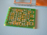
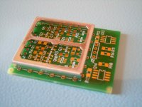
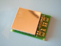
I managed to get the SMD version done, see attachment, but it's going to be a while before I'll populate the boards and test.
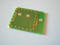
The boards are two layers and the bottom layer is a ground plane for the most part. Most of the silicon used is dual BJTs and current mirror duals for temperature tracking. The JFETs are singles because the Linear Systems parts are not so easy to procure here. The shielded box will be filled with a thermal gap filler pad and resistor on the bottom side of the board are used to fine tune the matching on bias current of the input stage and to set the bias of the output stage.
I also did a first stage only version of the board that fits into the shielded box footprint. It may be useful in some applications...
Stay tuned, but don't hold your breath")
Giorgio
The boards are two layers and the bottom layer is a ground plane for the most part. Most of the silicon used is dual BJTs and current mirror duals for temperature tracking. The JFETs are singles because the Linear Systems parts are not so easy to procure here. The shielded box will be filled with a thermal gap filler pad and resistor on the bottom side of the board are used to fine tune the matching on bias current of the input stage and to set the bias of the output stage.
I also did a first stage only version of the board that fits into the shielded box footprint. It may be useful in some applications...
Stay tuned, but don't hold your breath
Giorgio
Attachments
- Home
- Source & Line
- Analog Line Level
- Discrete Opamp Open Design