You are right about the sound, however there is a different cause than harmonic amplitude.Well then, let me throw this out there --->
One of the reasons for going low gnfb -in my mind- wa to get a constant amount of fb at all frequencies. back in the day, I didnt have such good test equipment for measuring distortion.
I thought that the way sound was described sort of followed the thd curve. --- best at low freqs and progressively worse as the freqs when higher.... that high freq rise at the top end. Still a characteristic of many amps -- pre or power. As we know there are many mechanisms at work.
But limiting this to just the thd and amount of feedback here -- What if -- the harmonic structure did not change with freq ?? What ever the relationship between harmonics at low or mid was the same at the high freqs? Same ratios etc.
Wouldnt that have a sameness to the sound across the audible band? No more, the mids sound this way and the highs sound that way. The character would be the same/similar.
In fact, that is what you get in test performance and in listening results. If the harmonics are high enough to hear or the chain/system has harmonics high enough levels to hear differences. there is no other way to get this kind of favorable result (is there?)... assuming a falling open loop within audio feq band and varying feedback margins/amount of etal.
Thx-RNMarsh
Well then, let me throw this out there --->
One of the reasons for going low gnfb -in my mind- wa to get a constant amount of fb at all frequencies. back in the day, I didnt have such good test equipment for measuring distortion.
I thought that the way sound was described sort of followed the thd curve. --- best at low freqs and progressively worse as the freqs when higher.... that high freq rise at the top end. Still a characteristic of many amps -- pre or power. As we know there are many mechanisms at work.
But limiting this to just the thd and amount of feedback here -- What if -- the harmonic structure did not change with freq ?? What ever the relationship between harmonics at low or mid was the same at the high freqs? Same ratios etc.
Wouldnt that have a sameness to the sound across the audible band? No more, the mids sound this way and the highs sound that way. The character would be the same/similar.
In fact, that is what you get in test performance and in listening results. If the harmonics are high enough to hear or the chain/system has harmonics high enough levels to hear differences. there is no other way to get this kind of favorable result (is there?)... assuming a falling open loop within audio feq band and varying feedback margins/amount of etal.
Thx-RNMarsh
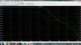
Do you think that an amp with the loop gain like this would sound better?
Damir
Attachments
But music or speech isn't white. I would think you'd have to take into account the power spectrum and further weight the more audible frequencies.
Just dont see the down side of having more loop gain where there is more energy hence higher signal amplitudes and increased distortion.
Thanks
-Antonio
Just dont see the down side of having more loop gain where there is more energy hence higher signal amplitudes and increased distortion.
Thanks
-Antonio
When the same amount of gnfb is used at all freqs, the distortion harmonics are alike at all freqs.; Same level and number and relationship/ratio. I believe this type of distortion pattern is well accepted as best sounding.
As I have said in earlier comments -- levels below -100dB are not audible to me and would be a desireable goal for all parts of the recording/playback system - keeping the total accumilated system thd below audibility.
Sorry but SIMs dont count. Only actual, live operating circuits and systems.
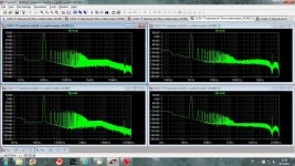
Here is a moderate gnfb line level amp that has the same THD and same harmonic structure at all freqs in the BW of interest. Only 2H and 3H. The important issue is that it looks the same at any freq tested...same level and number of harmonics and relative levels to one another.
Anyway, this characteristic is why, IMO, amps with low or no gnfb are liked by so many people.
Thx-RNMarsh

As I have said in earlier comments -- levels below -100dB are not audible to me and would be a desireable goal for all parts of the recording/playback system - keeping the total accumilated system thd below audibility.
Sorry but SIMs dont count. Only actual, live operating circuits and systems.
Here is a moderate gnfb line level amp that has the same THD and same harmonic structure at all freqs in the BW of interest. Only 2H and 3H. The important issue is that it looks the same at any freq tested...same level and number of harmonics and relative levels to one another.
Anyway, this characteristic is why, IMO, amps with low or no gnfb are liked by so many people.
Thx-RNMarsh
Last edited:
Sorry but SIMs dont count. Only actual, live operating circuits and systems.
But somewhere we have to start when design, and then do the measurement on the built amp. I hope you do not advocate to design without simulation?
Damir
When the same amount of gnfb is used at all freqs, the distortion harmonics are alike at all freqs.; Same level and number and relationship/ratio. I believe this type of distortion pattern is well accepted as best sounding.
As noted by a previous poster, you (and the many others who support this theory) miss that the frequency spectrum of music is not white. A circuit with measured frequency-independent distortion characteristics will in fact distort the bass range of real music more than the high-frequency portion.
Samuel
Seems reasonable. However, there is also a continuity that doesnt exist in any other type of distortion pattern. A sameness of character from top to bottom. What I am describing does not sound/heard as you describe.... worse in the bass. So maybe I am not characterizing it well enough. or weighting is something that lends a more constant or even quality. Well, its been easy to hear a pattern of distortion change that is uncharacteristci sounding from the falling open-loop gain etc and its distortion pattern. Worse or better.... it is different from typical pattern often found..... A flat thd plot vs one that rises at the higher freqs.
Thx-RNmarsh
Thx-RNmarsh
As I have said in earlier comments -- levels below -100dB are not audible to me and would be a desireable goal for all parts of the recording/playback system - keeping the total accumilated system thd below audibility.
What if the rising thd plot still is below -100dB at the highest frequency you are able to perceive ?
What if the rising thd plot still is below -100dB at the highest frequency you are able to perceive ?
Then you are on double-safe ground. And, would focus on construction, parts selection, shielding, grounding, interfacing, impedances, loading, controls, power supply, etc to not spoil the pristine amp. The goal then being to have the entire system -from source to speaker - not accumulate any issues that would intrude.
-Thx-RNMarsh
Last edited:
But somewhere we have to start when design, and then do the measurement on the built amp. I hope you do not advocate to design without simulation?
Damir
I dont know about that. Hewlett and Packard didnt design thier first instrument on a computer SIM. ETC. I have never designed any audio circuit by doing a SIM. I designed one complex filter (which won the patent prize) on a SIM and had it built and shipped many to customers... about a year later, I measured it and it was exactly as the SIM predicted. The patent was based on SIM.
But audio isnt that complex. If you know your goal and you know how to get it, then just do it and make it. A hand held calculator is all I use. I have a lot of test equipment over the years... they teach me and books teach me what others did. I am most interested in exploring ideas and concepts. Now if you had to make an IC, then SIM is the best way and now the only way. But experience still plays a large role as to what to do on the SIM.
Accumulated knowledge and mentoring goes on... whether IC or descrete. It's not unlike a Medical Doctor who, after years of study, mentoring and experience gets really good at what he does. As I see it, this forum is a lot about mentoring and ought to be doing more of it.
Thx-RNMarsh
Last edited:
RNM arsh,
I think that you would have to add that the sim is only as good as the information input into it. As the saying goes, garbage in garbage out..... If the models being used do not contain all of the variables necessary to get an accurate result is the result worth the time? This is no different from a mathematician rounding off all the steps in a formula and wondering why his rocket missed the moon, accuracy is in the inputs.
I think that you would have to add that the sim is only as good as the information input into it. As the saying goes, garbage in garbage out..... If the models being used do not contain all of the variables necessary to get an accurate result is the result worth the time? This is no different from a mathematician rounding off all the steps in a formula and wondering why his rocket missed the moon, accuracy is in the inputs.
I dont know about that. Hewlett and Packard didnt design thier first instrument on a computer SIM. ETC. I have never designed any audio circuit by doing a SIM. I designed one complex filter (which won the patent prize) on a SIM and had it built and shipped many to customers... about a year later, I measured it and it was exactly as the SIM predicted. The patent was based on SIM.
But audio isnt that complex. If you know your goal and you know how to get it, then just do it and make it. A hand held calculator is all I use. I have a lot of test equipment over the years... they teach me and books teach me what others did. I am most interested in exploring ideas and concepts. Now if you had to make an IC, then SIM is the best way and now the only way. But experience still plays a large role as to what to do on the SIM.
Accumulated knowledge and mentoring goes on... whether IC or descrete. It's not unlike a Medical Doctor who, after years of study, mentoring and experience gets really good at what he does. As I see it, this forum is a lot about mentoring and ought to be doing more of it.
Thx-RNMarsh
I am completely with you in that, but it was a time ago when spice was not available free of charge as now. I am talking about DIY not professionals circuit designer were spice was available much earlier. I worked in telecommunication and electronic was my whole life hobby and I started to use and learn spice simulator less then two years ago and I am 68 old, so its never to late to learn new staff. For the skill electronic designer its enough to use a hand held calculator, but then you have to build the thing to see if it work as it suppose to work and with simulator you can tray many different combinations and fast by it. I know a simulation is good as the one using it is good and as the models are good, but it fascinate me now as I can try many new ideas with no need to built it all.
BR Damir
RNM arsh,
I think that you would have to add that the sim is only as good as the information input into it. As the saying goes, garbage in garbage out..... If the models being used do not contain all of the variables necessary to get an accurate result is the result worth the time? This is no different from a mathematician rounding off all the steps in a formula and wondering why his rocket missed the moon, accuracy is in the inputs.
You are talking details... I was talking concept. but I did address your detail..... experience goes into a successful SIM. Could I do what Scott W. does at his level of detail where he works. No way.
What I can do well, is look at topologies, figure that a certain class (differential) is best and there are three versions of it. exploring which was best lead me to what is now called the current mode fb circuit topology. And, part of that decision was the desire to have constant gnfb at all freqs. It turned out that it has other benefits ... more in HF and RF. But within it's pro-con for audio, it has solutions. In IC form it is hard to do and isnt the best for many apps. The results you get with any of the differentail family of circuit topologies is always in the details.
So I went into R&D technical management side of things where I could explore concepts and ideas and do problem solving on that level and leave the details to the specialists.
Thx-RNMarsh
Last edited:
Richard,
I agree with what you are saying and you do have much more experience than most with our without the simulations. On the point of the current mode NFB circuit Doug Self just flamed that completely as a non starter on his thread asking questions about added topics for his book. He was adamant that it was a lost cause and had no hope of competing with a voltage mode feedback topology. Check that thread out, you may find it interesting.
Steven
I know he says that in his books... and thus doesnt cover it in detail... just acknowledges its existence and moves on. C-Mode fb is an option that has its pro-con like all other topologies. It has found a home in the IC opamp arsenal of the opamp makers especially in higher freqs and higher speed amps and interfaces.... like adc/dac and RF. All analog IC makes have them now as an adjunct to their line of VFb amps. It needs to get optimized for audio... too bad he doesnt explore its potential more. Other noted designers have done so and they have also written books. He is also against MOSFETs while others find them better for output stage. Doesnt like jFEts on input either. So, get all the sides and try them for yourSelf. Like Bob Cordell. Outside of audio and at higher freqs is the nitch for current-mode. Thats where its strengths gain ground.
It all depends on your design goals and thier technical priorities as to what you think is more important for the best sound. The diff input VFB is probably the best known, the best understood and offers the most bang for the buck. And, you can get tightly matched devices.
Thx-RNMarsh
It all depends on your design goals and thier technical priorities as to what you think is more important for the best sound. The diff input VFB is probably the best known, the best understood and offers the most bang for the buck. And, you can get tightly matched devices.
Thx-RNMarsh
Last edited:
Take a look at Bob Cordells book to help get a total overall balanced view. "Designing Audio Power Amplifiers" [McGraw-Hill).
And, there are many excellent developed cmfb circuits here in the DIYAUDIO forums. Truely excellent work being done to optimize them.
With these are Diamond buffers and Diamond amp configurations and complimentary push-pull and similar cmfb topologies.
Thx-RNMarsh
And, there are many excellent developed cmfb circuits here in the DIYAUDIO forums. Truely excellent work being done to optimize them.
With these are Diamond buffers and Diamond amp configurations and complimentary push-pull and similar cmfb topologies.
Thx-RNMarsh
Last edited:
Richard,
I do have that book and I have seen that Cordell does talk about the subject. Even in the thread I mentioned Bob pops in from time to time and the two of them do disagree about certain things, it is rather interesting to see the interaction between them. High Performance Loudspeakers by Martin Colloms is another very good read to go with these two authors.
I do have that book and I have seen that Cordell does talk about the subject. Even in the thread I mentioned Bob pops in from time to time and the two of them do disagree about certain things, it is rather interesting to see the interaction between them. High Performance Loudspeakers by Martin Colloms is another very good read to go with these two authors.
Where is this thread please?On the point of the current mode NFB circuit Doug Self just flamed that completely as a non starter on his thread asking questions about added topics for his book.
- Home
- Source & Line
- Analog Line Level
- Discrete Opamp Open Design