That looks good, albeit with a heavy RF emphasis. I'd order it in a heartbeat if I felt a little richerFor all interested, a new book appeared:
Matthias Rudolph, Christian Fager - Nonlinear Transistor Model Parameter Extraction Techniques. ISBN: 0521762103 (13 MB)
"Achieve accurate and reliable parameter extraction using this complete survey of state-of-the-art techniques and methods. A team of experts from industry and academia provides you with insights into a range of key topics, including parasitics, intrinsic extraction, statistics, extraction uncertainty, nonlinear and DC parameters, self-heating and traps, noise, and package effects. Learn how similar approaches to parameter extraction can be applied to different technologies. A variety of real-world industrial examples and measurement results show you how the theories and methods presented can be used in practice. Whether you use transistor models for evaluation of device processing and you need to understand the methods behind the models you use, or you want to develop models for existing and new device types, this is your complete guide to parameter extraction."
Got any simpler examples which demonstrate this?The Boxall in practice achieves lower THD figures thats why its appealing to use.
Super TIS is a ve..ery specialised application that only shows pp zillion THD into 50M & greater loads.
I just gave the dual, through-hole version for PCB fabrication today - probably a month for bare PCBs and a week or two after that for assembly and test. I'm hoping it will do OK in line stages in CDPs, DACs, soundcards, etc. - anything with a high-Z load. It could in principle drive low-Z headphones with a heftier output pair and higher output stage bias, though it wasn't designed for that.
Meanwhile, I've upgraded the SMD version to use Rohm IMX2/T2A duals in SC74 packages, which have higher (300 mW) Pd. I'll probably send it out for fabrication only after the through-hole version comes back and passes sanity checks.
Interesting, I'd like to play with this one as well, if that would be okay. I could probably even do a two sided version in a SIP-8 dual opamp format, similar to my layout. I could volunteer to look at higher output bias version. As you can see in my prototype, I'm using DIP14/16 heatsinks to bolster the heat dissipation of a SOT223 device. Does anyone have a recommended complementary SOT223 device? I have tried using BCP53-16 and BCP56-16 from On and feel these are good, but would appreciate other recommendations. The SOT223 seems to me to be a good size / Pd tradeoff. If these are good for output devices, then I might buy a bunch.
Also, thanks for the information on how to qualify the design. I'm sure I'll have more questions later, but the gives me enough to go on for now.
Last edited:
Based on a just the Data Sheets, the NXP PBSS8110Z ( http://www.nxp.com/products/bipolar...ransistors_single_npn/PBSS8110Z.html#overview ) and PBSS9110Z ( http://www.nxp.com/products/bipolar...ransistors_single_pnp/PBSS9110Z.html#ordering ) look like possibilities. (The same devices seem to be available in SOT-23 as PBSS8110T/PBSS9110T.) I'd like to know if anybody has first-hand experience.. . . Does anyone have a recommended complementary SOT223 device? I have tried using BCP53-16 and BCP56-16 from On and feel these are good, but would appreciate other recommendations. . . . .
Dale
Does anyone have a recommended complementary SOT223 device?
Fairchild PZTA42/92. Same chip as MPSA42/92.
Based on a just the Data Sheets, the NXP PBSS8110Z ( PBSS8110Z :: NXP Semiconductors ) and PBSS9110Z ( PBSS9110Z :: NXP Semiconductors ) look like possibilities. (The same devices seem to be available in SOT-23 as PBSS8110T/PBSS9110T.) I'd like to know if anybody has first-hand experience.
Dale
I'm using the NXP models for both these and the BCP and it doesn't do as well in my circuit, it's a about a 5dB difference.
The PZTA is heading in the right direction though, though I had to null out way more DC offset than with the other two candidates. Again, I used the NXP models. I wonder what qualities of the PZTA make it perform better than the BCP? If I can figure that out then I could see if there are models that perform even better.
5 dB difference in what parameter?I'm using the NXP models for both these and the BCP and it doesn't do as well in my circuit, it's a about a 5dB difference.
Dale
The 100 mA max collector current will be a factor to watch carefully if you are serious about driving Lo-Z headphones.Fairchild PZTA42/92. Same chip as MPSA42/92.
Dale
5 dB difference in what parameter?
Dale
Output THD @ 20kHz (according to LTSpice)
Got any simpler examples which demonstrate this?
Super TIS is a ve..ery specialised application that only shows pp zillion THD into 50M & greater loads.
Hello Kgrlee,
Do you have a copy of Dimitri's "Enhanced cascode Article".
I don't Pheonix. I'm new to diyaudio. A link would be appreciated or a PM. ThanksDo you have a copy of Dimitri's "Enhanced cascode Article".
Interesting, I'd like to play with this one as well, if that would be okay. I could probably even do a two sided version in a SIP-8 dual opamp format, similar to my layout. I could volunteer to look at higher output bias version.
Sure, you're welcome to try out anything. I'm guessing that a high-bias version that's able to drive low-Z loads will require through-hole TO-92 or TO-126 output devices, and the board size is a constraining factor. Presently, I'm at 14mm x 14mm using the Rohm IMX2/T2 duals, and the 2sk209 singles. I was able to route everything on one layer without vias, but had to remove pads 1 and 5 from the DIP8 footprint to create space.
It is conceivable that a 2-layer SMD DIP8 dual opamp is within reach, but it will be slightly larger because pads 1 and 5 are required.
one last question. I'd like to optimize an incarnation for use in Salen-Key filters. Is there a good rule of thumb in terms of load that approximates a wide variety of filter topologies? I was thinking that something in the 30K range would be normal (with a spike where you'd expect it) and was using 4.7K in my simulations. I thumbed through Self's book on the subject last night and didn't see anything in the opamp section where he goes through a bunch of current parts and discusses their relative merit. I have a feeling this answer is more difficult than what I'm asking for, but go easy on me
Does anyone have a recommended complementary SOT223 device?
I'm using 2SC5964 and 2SA2125 as they are the highest power rated devices in this package I have found so far and also have a huge Ft and decent Hfe but I don't know how advantageous any of this is. See some others from my list (all SOT223)
2STN1360 2STN2360 60v 3A 1.6W 130MHz 80 400
BCP55 BCP52 60v 1A 2W 150MHz 100 250 linear to 100mA, designed for AF
BCP56 BCP53 80v 1A 2W 150MHz 100 250 linear to 100mA, designed for AF
BCX55 BCX52 60v 1A 1W 150MHz 100 250 linear to 100mA, designed for AF
BCX56 BCX53 80v 1A 1W 150MHz 100 250 linear to 100mA, designed for AF
FTZ692B FTZ792A 70v 2A 2W 160MHz 300 800 linear to over 100mA
FTZ651 FTZ751 60v 3A 2W 140MHz 100 300 linear between 10-200mA
I'm sure you adjusted resistor values so you compared the transistor pairs at the same collector idle currents.Output THD @ 20kHz (according to LTSpice)
I still don't have a good intuitive feel for the parameter interactions in the cross-coupled output stage of SW-OPA (see atch image)
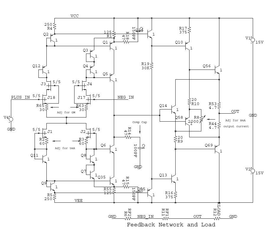
I recall reading somewhere that the output drivers (Q14 and Q58 in Post #1568) should be faster than the actual output devices (Q56 and Q69) for frequency stability. But for lowest distortion (and perhaps thermal stability) the seat of my pants says they should be the same as the output devices.
Rather than looking for output devices that minimize distortion, should we be looking for pairs that work best in this topology, i.e. consider the compound-connected Q56/Q58 (and Q14/Q69) as single devices to be optimized?
Dale
bobaruni said:BCX56 BCX53 80v 1A 1W 150MHz 100 250 linear to 100mA,
This pair is also available in SOT89, smaller than SOT223, and with metal tab.
I'm sure you adjusted resistor values so you compared the transistor pairs at the same collector idle currents.
I still don't have a good intuitive feel for the parameter interactions in the cross-coupled output stage of SW-OPA (see atch image)
I recall reading somewhere that the output drivers (Q14 and Q58 in Post #1568) should be faster than the actual output devices (Q56 and Q69) for frequency stability. But for lowest distortion (and perhaps thermal stability) the seat of my pants says they should be the same as the output devices.
Rather than looking for output devices that minimize distortion, should we be looking for pairs that work best in this topology, i.e. consider the compound-connected Q56/Q58 (and Q14/Q69) as single devices to be optimized?
Dale
It's really just a diamond that bootstraps itself. Any stability issues would mainly be with Q14 and Q58 looking back into the emitters of the output devices which can look inductive as you approach Fbeta. The output stage breadboard had no problems, and at 8mA bias and 600 Ohm load still only had .01% distortion.
The Sziklai pair has feedback and in my experience is much more prone to oscillate, but the added gain typically reduces the distortion by a larger factor.
My experience as well with Sziklai. And the poorer ability to turn off an output device translates into a dynamic asymmetry that is somewhat bothersome at high frequencies. Bryston has used a triple compound that they have managed to make work, but it looks very temperamental in simulation.The Sziklai pair has feedback and in my experience is much more prone to oscillate, but the added gain typically reduces the distortion by a larger factor.
one last question. I'd like to optimize an incarnation for use in Salen-Key filters. Is there a good rule of thumb in terms of load that approximates a wide variety of filter topologies? I was thinking that something in the 30K range would be normal (with a spike where you'd expect it) and was using 4.7K in my simulations. I thumbed through Self's book on the subject last night and didn't see anything in the opamp section where he goes through a bunch of current parts and discusses their relative merit. I have a feeling this answer is more difficult than what I'm asking for, but go easy on me
Look at signal-to-noise at a given frequency to determine how sensitive it will be to impedances, and then make the determination about how the filter components will load the amp output. Then fold in the loading thereafter.
Every situation is different, and I know of no rule-of-thumb. Lower Z is always lower noise, but depending on where the circuit is in the system you may be well-dominated by noise in the input signal already, so there may be no reason for heroic measures in the filter.
- Home
- Source & Line
- Analog Line Level
- Discrete Opamp Open Design