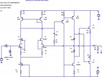
I've been trying to meet at least the spirit of Marshy's requirement for less active devices without spoiling the performance of the #2060 JFET990. Presently, it rivals SW-OPA ... at least in SPICE world ")
A key factor in this performance is the 'pure' Cherry compensation which keeps the Q10/15 output bases at very high Z.
Taking the VAS cascode reference to the emitter of Q16 helps and gets rid of one diode. It shows slightly less THD and better stability too. This type of cascode, used in the i/p as per Guru Wurcer, is responsible for good CMR & CM range.
Other small changes are ..
- Q13 becomes D2. R1 value is one area where the SPICE models are inaccurate. I'm certain a diode connected BJT will have less voltage drop than 1n4148/914. But its just a resistor value and this is our tweak point for output offset.
- Q16 is shown as BC557C instead of the 2n4403 cos it gives 100dB from 90dB distortion products. I doubt the difference will be seen in a real amp.
- C9 across the bias BJT tidies up O/L slightly which is obviously an obsession of mine. I try to keep caps small to minimize O/L recovery time.
J5 + R17 is just a CCS and could be replaced with a 0.5mA device provided it could withstand full VCC - VEE. Suggestions for this anyone?
Attachments
I've been trying to meet at least the spirit of Marshy's requirement for less active devices
J5 + R17 is just a CCS and could be replaced with a 0.5mA device provided it could withstand full VCC - VEE. Suggestions for this anyone?
I've been a fan of fet constant current 'diodes' since the '70's. The commercial ones (Siliconix) rated at 55volts are actually cascoded inside - thus the higher v rating- also have higher Zout and thats good for cmr. (for Q17, too) -RNMarshy
Last edited:
Thanks for this Mr. Marsh. It's certainly what's required to replace J5. I'm reminded I have some SPICE models for Siliconix diodes too.I've been a fan of fet constant current 'diodes' since the '70's. The commercial ones (Siliconix) rated at 55volts are actually cascoded inside - thus the higher v rating- also have higher Zout and thats good for cmr. (for Q17, too)
Presently, Q17 and resistor allows flexibility in choice of i/p LTP currents but a Siliconix diode would be perfect for production.
I'm quite a Luddite and in da old days would round up on young engineers whose designs had more bits than the products they replaced. Today, with SM, it's probably worth counting solder joints rather than bits but I still feel parts count is a significant indicator of reliability especially for a DIY item.
_____________________
This is a segue into another variant of JFET990. While investigating the 'bootstrapped cascode', I came across Baxandall Super Pair which suggested the Great Guru originally developed it for high Ro .. just what's required for 'pure' Cherry.
This little change
- gets rid of 2 more diodes and on preliminary tests
- appears more stable than #2060 & #2321.
- Also overload is even better though we are now at the stage of shoving more than +/- 15Vp down their throats.
CONS?
- Some careful balancing of input currents, current mirror resistors & R4 to get at least Vce=0.5V across important BJTs else the excellent O/L & THD is compromised
- Re-introducing another gain stage may cause stability problems. I haven't done a full stability analysis & investigation. The Baxandall Super Pair thread has many caveats.
- The current mirror has to use smaller resistors so now contributes more noise. But the BF862s & 20R resistors still dominate. May change if we run as much i/p current as SW-OPA. See Sam Groner's critique of Self's PA book for details.
ricardo.txt at #2306
Attachments
Last edited:
This is a segue into another variant of JFET990. While investigating the 'bootstrapped cascode', I came across Baxandall Super Pair which suggested the Great Guru originally developed it for high Ro .. just what's required for 'pure' Cherry.
This little change
In essence, Q16 is re-introduced as an emitter follower (as JE990) but w/o the need for an evil latching diode across the Miller cap. I apologise to GGB's disciples who want a more respectful description of the Master's work.
- gets rid of 2 more diodes and on preliminary tests
- appears more stable than #2060 & #2321.
- Also overload is even better though we are now at the stage of shoving more than +/- 15Vp down their throats.
CONS?
Getting to the stage where I regret being a beach bum
- Some careful balancing of input currents, current mirror resistors & R4 to get at least Vce=0.5V across important BJTs else the excellent O/L & THD is compromised
- Re-introducing another gain stage may cause stability problems. I haven't done a full stability analysis & investigation. The Baxandall Super Pair thread has many caveats.
- The current mirror has to use smaller resistors so now contributes more noise. But the BF862s & 20R resistors still dominate. May change if we run as much i/p current as SW-OPA. See Sam Groner's critique of Self's PA book for details.
ricardo.txt at #2306
Baxandall (historically, properly attributed to the late Frank S. Boxall who invented it in ~1957) has drawbacks compared to the bootstrapped cascode (the latter also developed long before Hawksford's popularizations among audio workers). The bootstrapped cascode reduces base width modulation, Boxall does not. Transconductance overall is reduced, comparatively. For both topologies the effectiveness of the stage depends on how large the impedance in the main device's emitter is (higher is better for recovering more of the base current loss of the main device, as the returned current divides between the main emitter impedance and the external impedance).
Stability-against-oscillation issues, as you noted for Boxall, exist for both approaches (see my recent note on a mostly-air circuit using the bootstrapped cascode, which needed signficant R in series with the output collector for stability, and various remarks about stabilizing Boxall [-Larson-Baxandall-Shallow etc.] in the Baxandall Super Pair thread you referenced, and elsewhere (?) ).
An advantage of Boxall is the partial temperature compensation afforded by the opposing Vbe's. I stumbled on it way late by asking a what-if when using a complementary transistor for temp-comped bias, as to what would happen if something were done with the bias device's collector current?
It was bad enough to discover that Larson at Tektronix and PJ Baxandall had stolen the idea when I was about 18, but even worse when I found the Boxall ref.... just what's required for 'pure' Cherry.
... Q16 is re-introduced as an emitter follower (as JE990) but w/o the need for an evil latching diode across the Miller cap.
Referencing the VAS Miller cap to the output node, a la AD797, is right on the money - at least, that's what LTSpice says.
Regarding the diode across the Miller cap, I thought it was a Baker antisaturation clamp for the VAS. The Blameless-style voltage-follower VAS seems to work fine without the diode, and getting rid of its non-linear junction capacitance helps reduce H3 quite a bit.
It also helps to use separate current sources for the LTP and VAS, to reduce the possibility of overload/clipping transients spilling over from the VAS into the LTP. I think Douglas Self went wrong in the Blameless by using a shared biasing scheme for both LTP and VAS current sources.
I think Douglas Self went wrong in the Blameless by using a shared biasing scheme for both LTP and VAS current sources.
Agreed
Baxandall (historically, properly attributed to the late Frank S. Boxall who invented it in ~1957) has drawbacks compared to the bootstrapped cascode (the latter also developed long before Hawksford's popularizations among audio workers). The bootstrapped cascode reduces base width modulation, Boxall does not. Transconductance overall is reduced, comparatively. For both topologies the effectiveness of the stage depends on how large the impedance in the main device's emitter is (higher is better for recovering more of the base current loss of the main device, as the returned current divides between the main emitter impedance and the external impedance).
Stability-against-oscillation issues, as you noted for Boxall, exist for both approaches (see my recent note on a mostly-air circuit using the bootstrapped cascode, which needed signficant R in series with the output collector for stability, and various remarks about stabilizing Boxall [-Larson-Baxandall-Shallow etc.] in the Baxandall Super Pair thread you referenced, and elsewhere (?) ).
An advantage of Boxall is the partial temperature compensation afforded by the opposing Vbe's. I stumbled on it way late by asking a what-if when using a complementary transistor for temp-comped bias, as to what would happen if something were done with the bias device's collector current?
Hello Brad ,
The Boxall in practice achieves lower THD figures thats why its appealing to use.
Hello Brad ,
The Boxall in practice achieves lower THD figures thats why its appealing to use.
If one drives Boxall with a high-Z source, like the collector of another transistor, to essentially remove the base-width modulation effect on Vbe, the performance can be fantastic. See the Danyuk reference in Walt's bibliography for example.
As simply a gain stage with an emitter R in the output device, although there can be some cancellation of even-order due to the complementary devices, I was a little disappointed.
Both stages look not-too-elaborate at first glimpse, but the details of biasing are one of the necessary complexities for both.
Works in real life too. Especially for xover distortion. It's no longer a Miller cap but Prof. Edward Cherry's scheme. Baxandall & Self now promote their TMC bastardised scheme which is Miller / Cherry but this doesn't give the full advantages of pure Cherry.Referencing the VAS Miller cap to the output node, a la AD797, is right on the money - at least, that's what LTSpice says.
Works without the diode in Self's power amps cos the output compound emitter-followers/CFPs. Not with the single Class B stage here and in JE990. Horrible O/L... the diode across the Miller cap, ... The Blameless-style voltage-follower VAS seems to work fine without the diode, and getting rid of its non-linear junction capacitance helps reduce H3 quite a bit.
Most of this project has been 'how to get rid of evil Cob effects without introducing latching' It's key to getting SOTA SW-OPA performance from a stone age circuit.
Jensen claims this in his AES paper. I don't see any evidence in my sims and don't recall any problems from Jurassic REAL life.It also helps to use separate current sources for the LTP and VAS, to reduce the possibility of overload/clipping transients spilling over from the VAS into the LTP. I think Douglas Self went wrong in the Blameless by using a shared biasing scheme for both LTP and VAS current sources.
Anyone got evidence? Either sim or REAL life
#2323 was a long evolution from JE990+Scott's FET i/p. Each change was tested ala #2306. I don't do fashion changes. Only in response to something which needs improving.
If I get rid of another 2 BJTs I'll meet Marshy's requirements for a production OPA
OK. I'm cheating by not counting CCS diodes as actives. This is essentially #2323.If one drives Boxall with a high-Z source, like the collector of another transistor, to essentially remove the base-width modulation effect on Vbe, the performance can be fantastic. See the Danyuk reference in Walt's bibliography for example.
But there are a number of interacting factors in any non-trivial circuit. You can get rid of the evil effects of modulated Cob in several ways. It is most evil when the Common Emitter stage is current driven. You see this if the VAS is a simple PNP with no extra bells & whistles.
Cascoding as in #2321 and my previous submissions, stops Cob from being modulated. Just adding this to the single PNP gives SW-OPA performance with a few tweaks.
Another 'cure' is to voltage drive. Original JE990 and the FET i/p Wurcer derivative do this cos the extra emitter follower on the VAS. If you remove the evil Miller cap diode, you get SW-OPA performance with a few tweaks. Alas you need the diode if you want clean O/L.
Baxandall Super Pair may just be providing a measure of voltage drive. This may be a simpler explanation than 're-inserting the base current into the emitter'. The residuals, even at very high CL gain, for all 3 (cascode versions, Baxandall, 'JE990 w/o diode') are very similar and at levels which suggest they won't be seen above noise in REAL life.
Comparisons are complicated cos the cascodes as in #2321 & #2060 have one less gain stage so at least 20dB less loop gain at LF.
My main interest in Baxandall Supa is SW-OPA performance w/o nasty overload (already achieved with #2321 & previous) but with two less diodes
. Gotta finish checking stability.
Last edited:
Hello Richard,
Have you seen this thread, its quite interesting.
http://www.diyaudio.com/forums/solid-state/209658-has-anyone-seen-front-end-before.html#post2961888
Have you seen this thread, its quite interesting.
http://www.diyaudio.com/forums/solid-state/209658-has-anyone-seen-front-end-before.html#post2961888
To be more precise, I should say that I meant using Boxall as a compound cascode, with the high Z drive from the collector to the main Boxall emitter. See Danyuk's paper for an example.This is essentially #2323.
But there are a number of interacting factors in any non-trivial circuit. You can get rid of the evil effects of modulated Cob in several ways. It is most evil when the Common Emitter stage is current driven. You see this if the VAS is a simple PNP with no extra bells & whistles.
Cascoding as in #2321 and my previous submissions, stops Cob from being modulated. Just adding this to the single PNP gives SW-OPA performance with a few tweaks.
Another 'cure' is to voltage drive. Original JE990 and the FET i/p Wurcer derivative do this cos the extra emitter follower on the VAS. If you remove the evil Miller cap diode, you get SW-OPA performance with a few tweaks. Alas you need the diode if you want clean O/L.
Baxandall Super Pair may just be providing a measure of voltage drive. This may be a simpler explanation than 're-inserting the base current into the emitter'. The residuals, even at very high CL gain, for all 3 (cascode versions, Baxandall, 'JE990 w/o diode') are very similar and at levels which suggest they won't be seen above noise in REAL life.
Comparisons are complicated cos the cascodes as in #2321 & #2060 have one less gain stage so at least 20dB less loop gain at LF.
My main interest in Baxandall Supa is SW-OPA performance w/o nasty overload (already achieved with #2321 & previous) but with two less diodes
Or [edit] the schematic that PHEONIX linked to
Last edited:
Hmmm..m. Dun get rid of any active devices. Does get rid of 2 devices in the forward path so lose loadsa Loop Gain.To be more precise, I should say that I meant using Boxall as a compound cascode, with the high Z drive from the collector to the main Boxall emitter. See Danyuk's paper for an example.
Or the schematic that PHEONIX linked to
Dunno if you need all dis complexity for a full OPA. The fully obfuscating website, Super TIS, is more interesting cos it discusses compensation.
Worth a play I suppose. Doubt if it will provide better performance than #2323, #2060, SW-OPA etc
But if the same performance, but less devices ... or even just less devices in the forward path (so better stability) I might steal ... I mean present an improved version in one of my future efforts.
Ain't SPICE wunnerful
Last edited:
I'm not blanket-endorsing any of these designs btw, just showing examples in lieu of having to draft things.Hmmm..m. Dun get rid of any active devices. Does get rid of 2 devices in the forward path so lose loadsa Loop Gain.
Dunno if you need all dis complexity for a full OPA. The fully obfuscating website, Super TIS, is more interesting cos it discusses compensation.
Worth a play I suppose. Doubt if it will provide better performance than #2323, #2060, SW-OPA etc
But if the same performance, but less devices ... or even just less devices in the forward path (so better stability) I might steal ... I mean present an improved version in one of my future efforts.
Ain't SPICE wunnerful
And in particular, I'm not moved by efforts to eliminate parts when doing this sort of stuff. But that's just me --- I've done my share of minimalist designs for cost reduction in mega-mass-production and it's boring as hell
...
Jensen claims this in his AES paper. I don't see any evidence in my sims ...
If I get rid of another 2 BJTs I'll meet Marshy's requirements for a production OPA
What I have in mind is something like the attached schematic. As long as the rails are high enough and the swings don't get to within several volts of the rails, it simulates very well indeed for 12 actives. I haven't checked hard overload/clipping conditions, and all the usual diode clamps are omitted.
I sometimes cheat on real builds by using a band-gap reference to generate 1.25V instead of a BAV99, so it's fair game not to count diodes as actives.
Attachments
Last edited:
I like the challenge of getting similar or better performance with a simpler circuit. I'm anal about PCB layouts, and the simpler it is, the less I'll agonise over whether there's better routing for LN & EMI.And in particular, I'm not moved by efforts to eliminate parts when doing this sort of stuff. But that's just me --- I've done my share of minimalist designs for cost reduction in mega-mass-production and it's boring as hell
And I don't do it for cost reduction but for reliability & hopefully better performance.
Beats doing crossword puzzles.
linux, I like that circuit cos its closer to what I've tried in real life.What I have in mind is something like the attached schematic. As long as the rails are high enough and the swings don't get to within several volts of the rails, it simulates very well indeed for 12 actives. I haven't checked hard overload/clipping conditions, and all the usual diode clamps are omitted.
If you have nasty O/L behaviour, try a clamp diode from collector Q5 to base Q1. Also an emitter resistor for Q5 is useful for stability.
Why the liking for this FET o/p topology?
Can you post the LTspice *.asc file and models?
For all interested, a new book appeared:
Matthias Rudolph, Christian Fager - Nonlinear Transistor Model Parameter Extraction Techniques. ISBN: 0521762103 (13 MB)
"Achieve accurate and reliable parameter extraction using this complete survey of state-of-the-art techniques and methods. A team of experts from industry and academia provides you with insights into a range of key topics, including parasitics, intrinsic extraction, statistics, extraction uncertainty, nonlinear and DC parameters, self-heating and traps, noise, and package effects. Learn how similar approaches to parameter extraction can be applied to different technologies. A variety of real-world industrial examples and measurement results show you how the theories and methods presented can be used in practice. Whether you use transistor models for evaluation of device processing and you need to understand the methods behind the models you use, or you want to develop models for existing and new device types, this is your complete guide to parameter extraction."
Matthias Rudolph, Christian Fager - Nonlinear Transistor Model Parameter Extraction Techniques. ISBN: 0521762103 (13 MB
)"Achieve accurate and reliable parameter extraction using this complete survey of state-of-the-art techniques and methods. A team of experts from industry and academia provides you with insights into a range of key topics, including parasitics, intrinsic extraction, statistics, extraction uncertainty, nonlinear and DC parameters, self-heating and traps, noise, and package effects. Learn how similar approaches to parameter extraction can be applied to different technologies. A variety of real-world industrial examples and measurement results show you how the theories and methods presented can be used in practice. Whether you use transistor models for evaluation of device processing and you need to understand the methods behind the models you use, or you want to develop models for existing and new device types, this is your complete guide to parameter extraction."
Last edited:
No, I don't know them.Hello Brad
Out of curiosity do you know the guys who design /Layout the Audio Research products.
- Home
- Source & Line
- Analog Line Level
- Discrete Opamp Open Design