Haven't really looked at noise with SPICE. I expect similar noise to SW-OPA if running the same input currents. Presently I'm only using 2x1.2mA while SW-OPA has 2x5mAVery good numbers and down from 20 to only 15 transistors per channel, too. And, drives low Z loads. Nice cmr number.
S/N ? and at what gain where your numbers done with? x100? What is cmr with gain = x10?
The gain structures are very similar if running the same currents & bandwidths (OK they aren't but sorta are for noise
") )
)There has to be a reason for a new circuit and I figured this is the Golf GTi to Scotts Audi A3 [*] so I'm going for less current and a hair shirt stone age approach
I'm also nervous about increasing the zillion V/us slews as I think both are already in OPA627 & AD797 layout & decoupling territory.
eg it's likely most existing circuits using JE990 will have clean & dirty earths joined at the OPA cos the on board 0u1. But this is unlikely to give optimum results with AD797/OPA627 or these circuits.
Distortion 20kHz 10Vp 600R @ 100x gain cos its difficult to get either design to show more than -120dB products on less gain.
.. except the 15R results which were Voltage Follower. This 3.162 Vp test is really small PA territory but I wanted some numbers to compare with NWavguy's O2 headphone amp. Also to see what happens if you run deep Class B
CMR at 10x gain is 107dB to 20kHz. The Texas/AD sim test circuits (which I assume have some similarity to how they test in real life are 1x. It's all roughly scaled to NFB. So 20dB less at 10x gain 40dB less at 100x etc as you'd expect. And don't forget its a sim with 0.0001% matched FETs & resistors so I don't really believe we could build something with similar CMR to AD797/OPA627 like the numbers claim.
[*] Of course SW-OPA is really Mercedes SLK rather than these boy racer examples.
Well, you can, if you include real parasitics everywhere! Normal test circuits are riddled with assumptions, like perfect, non-noisy power supplies, perfect non-inductive connections, every ground is a perfect ground, zero capacitive coupling between parts of the circuit, no aspect can act as antennae, and on and on ...Do I believe this SPICE sh*t?
As apart from the 15R results, the distortion products are mostly around -100dB, it is likely that this and SW-OPA will be as critical as AD797 and OPA627 for layout & decoupling. In many situations, layout & decoupling is the MOST important factor in noise & distortion.
It's a wonder that Spice does as well as it does at times ...
Frank
Thanks Frank. No traction control at present. And thanks for your many tips and inspiration along the way too.BTW, Richard, very nice effort in doing that development! I'll give it a bit of a thrash, try not to wrap it around a tree ...
Much of the time its me staring at the results and asking, "Do I believe that?"
Trying to avoid having an inductor on the output like a power amp which would make life so much easier. But SMD inductors are nasty and IMHO only suitable for EMI/RFI.
LTspice 'AC Analysis' dun always make sense compared to 'Transient' for dis stability stuff. I'm leaning towards 'Transient' for real life. Or it may just be stupid me
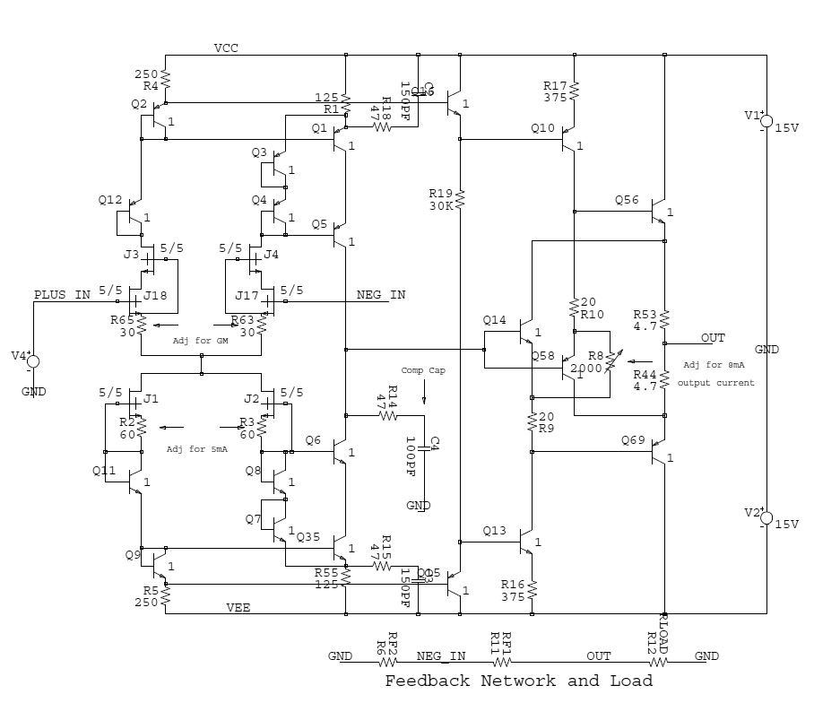
I'm posting what is very near a final [*] design for a JFET 990. Such beasts have appeared in the past so what's different?
[*] in as much as anything which hasn't been built can be called final
Lots of good stuff here, worth a build. We could simplify but let's try it first.
No worries .. I'm impressed by the energy you're throwing into this .. !!
Frank
Ditto.. so much in such a short time.
Wanna suggest some other criteria? Preferably some can translate to design objectives.The main focus of preamp s is low noise, due to extremely high amplification factors and extremely high input impedance due to fragile input currents.
Don't think we've even touched on 'low noise'. Nothing suggested so far has voltage noise within 3dB of AD797 though of course much better current noise cos FET i/p
Thanks kf_tam,Hi Lineup,
Mr. Wurcer's latest is at #1568, with a slight mod to prevent latch up at #1776. The circuit discription is at #1675. In case you are wondering for a fully complementary frontend, that frontend is at #454, (though the symbols for P channel JFETs were wrong.)
Besides, he also published a FET input version of the JE990 discrete OPAMP at #1510
Thanks kf_tam,
your post is a blessing. Well done.
Now, I will go have a look
Regards,
Edward Tam
your post is a blessing. Well done.
Now, I will go have a look
Thanks kf_tam,
your post is a blessing. Well done.
Now, I will go have a look
Hi Lineup,
Thanks. I have been waiting to see what you will add the party
Actually, I missed some preliminary sim results from Mr. Wucer but couldn't edit the post.
So here they are: N-ch JFET without cascode#1380 & effect of cascode on PSRR #1542,
N-ch JFET with Rush cascode #1387,
full complementary JFET #1397
The N-ch JFET version was selected, and cascode was added formally #1558, then additional compensation added #1568, JCX's idea of compensation was tested #1725.
Currently Mr. Wucer is testing the output section (diamond buffer) in real life #22032 (as oppose to stimulation only
) possibly out of 2N4401/4403.BTW, a LTSPICE pack #1577 is also available for anyone to try.
Regards,
Edward Tam
In the above Q3, 4, 8, and 7 can be ordinary 1N914/1N4148. I think your list of posts included the single 1N914 diode needed to catch a power supply sequencing issue (with it there is no need to worry at all). Depending on particular application not all the compensation components are needed and an output Zobel network should be considered for difficult loads.
its Wurcer, not Wucer =) and I think he prefers Guru rather than Mr.
Actually I prefer to drop the Guru
. The name was originally German with an umlaut and a z. Such things were frowned upon by immigration.its Wurcer, not Wucer =) and I think he prefers Guru rather than Mr.
Sorry for this!
Being a former scientist, I prefer to remain completely neutral when reporting the development history
What I can add is not very advanced, Edward.Hi Lineup,
Thanks. I have been waiting to see what you will add the party
Actually, I missed some preliminary sim results from Mr. Wucer but couldn't edit the post.
------
Regards,
Edward Tam
But I have ideas ..... thats a start!
I have one solution regarding OPamp.
It is the link between the input differential and the VAS.
Warning!
I have not seen anyone use this approach before.
Not even John Curl.
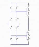
This solution can we see simplified in figure #1.
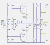
And see it in a working OPamp in figure #2.
There are both benefits and drawbacks.
The benefit it elegantly takes the gain of input stage
and combine it in second VAS into one point.
The drawback is it takes some volts out of Vas stage.
But
I like the idea very much.Let's call it Lineup's JFETspecial.
Attachments
I have not seen anyone use this approach before.
I have
http://www.diyaudio.com/forums/anal...screte-opamp-open-design-199.html#post3229102
http://www.diyaudio.com/forums/anal...screte-opamp-open-design-199.html#post3229421
And I have another one for you
Attachments
Last edited:
- Home
- Source & Line
- Analog Line Level
- Discrete Opamp Open Design