Sorry I didn't address this earlier ... did a quick take, so can't vouch for the accuracy, but for perfectly matched FETs the sim says 87dB up to 1MHz, then drops away to 60 by 3MHz ...What is the CMR of the SW-OPA? If -100DB for thd is a good number to shoot for, I think same (-100) would be good for CMR.
Frank
CMR
Its a starting point --- but need to know what input Z you used and what gain to be more meaningful later for apple to apple comparisons. Thx-RNM
Sorry I didn't address this earlier ... did a quick take, so can't vouch for the accuracy, but for perfectly matched FETs the sim says 87dB up to 1MHz, then drops away to 60 by 3MHz ...
Frank
Its a starting point --- but need to know what input Z you used and what gain to be more meaningful later for apple to apple comparisons. Thx-RNM
Mr. Marsh, could you detail YOUR method of measuring CMR? It doesn't seem to be usual method used by the OPA makers.Its a starting point --- but need to know what input Z you used and what gain to be more meaningful later for apple to apple comparisons.
Some circuit diagrams and/or sketches would be useful for us unwashed masses.
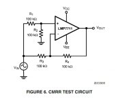
The circuit used was from TI's Application Note 1516: Pspice Universal Test Circuits -- from their National Semi division, 2009. If another circuit configuration is more appropriate, I'd be happy to apply it ...Its a starting point --- but need to know what input Z you used and what gain to be more meaningful later for apple to apple comparisons. Thx-RNM
Frank
Attachments
The circuit used was from TI's Application Note 1516: Pspice Universal Test Circuits -- from their National Semi division, 2009. If another circuit configuration is more appropriate, I'd be happy to apply it ...
Frank
That is fine... it is a standard configuration for cmr testing. With sim's you can have perfectly matched parts.
I wonder how I misled anyone about cmr --- My comments are not about the testing of it -- rather what constitutes a common-mode signal and where it can come from.... and thus, it is an important spec. for audio/music signals and amps. Thx-RNM
Last edited:
Hi Guys,
I just came across this interesting thread and thought some of my R&D might be of use to others, I have also been looking at building some discrete op amps with the purpose of an I/V for PCM63P-K and hopefully when funds permit, a balanced PCM1704U-K setup. Also for a high quality headphone Amp, I simulated quite a bit with the SK99B design and have tweaked it ever so slightly to drive a 32 Ohm load with lower distortion and lower voltage rails. I have designed and made a PCB for the SK99B (but not populated yet) using almost the same active devices as the original design (SMD output transistors and BAV99 diodes). I also designed a PCB using the SK99B design but Inverted (swapped PNP for NPN and reversed power rails and using SMD devices only. I did this because in LTspice, simulations predicted less distortion (I'm guessing because the VAS Is now NPN and has a more linear Hfe vs Ic curve. The Current mirror is done in a single matched device made especially for current mirrors by NXP and available from Element14 and digikey, BCM61B (2xNPN) and BCM62B (2xPNP).
Bob.
Hi Guys,
I just came across this interesting thread and thought some of my R&D might be of use to others, Bob.
All contributions are welcome. I've used those pre-connected current mirrors before, if you search back Stinius had some suggestions along similar lines.
Last edited:
Welcome to this thread, Bob. Please post your LTSpice *.asc with any associated models. It might be easier to put them all in a *.zip file.
You might like to compare your results with the various circuits investigated in this thread.
If you'll excuse my ignorance, what's a SK99B?
You might like to compare your results with the various circuits investigated in this thread.
If you'll excuse my ignorance, what's a SK99B?
If you'll excuse my ignorance, what's a SK99B
http://www.soundskulptor.com/pdf/sk99b-schematic.pdf:)
Delete the smilie, these look like JE990 based designs with a few different compensation ideas and parts list.
Guru Wurcer, this looks like a pretty namby-pamby CMR test.The circuit used was from TI's Application Note 1516: Pspice Universal Test Circuits -- from their National Semi division, 2009. If another circuit configuration is more appropriate, I'd be happy to apply it ...
How do AD measure the 130dB CMR for your AD797?
Without getting into discussions over Mr. Marsh's 'cmr', I think 20kHz THD at high level for a voltage follower is probably the most relevant test for audio. Would it need feeding from a high source R? If so, what's a good value?
I did a report for Calrec circa 1980 on this with caveats on the use of 5532/4 & TL07* in various circuits. One of the things which came out of that study was the latching behaviour of TL07* was far more obnoxious; especially in HP filters that might be overloaded. This millenium, LM4562 appears to behave similarly.
PS for yus unwashed masses, I'm looking at the latest AD797 datasheet and am again in awe of Guru Wurcer's masterpiece. We grovel at your feet.

And Scott, could you please bring back young Ludwig as soon as Halloween is over?
Last edited:
Guru Wurcer, this looks like a pretty namby-pamby CMR test.
How do AD measure the 130dB CMR for your AD797?
And Scott, could you please bring back young Ludwig as soon as Halloween is over?
Please worship is not necessary. There is a standard Teradyne (they make most of the big testers) test loop for all DC specs, I have not done that for years so I forgot the details. Tek had an op-amp curve tracer plug-in that could do this, slowly at -130dB.
That was Billy Budd (Terence Stamp). Melville was one of my high school faves.
Last edited:
bobaruni, please don't be discouraged by Guru Wurcer's comments. He's really much nicer than his avatar.Welcome to this thread, Bob. Please post your LTSpice *.asc with any associated models. It might be easier to put them all in a *.zip file.
You might like to compare your results with the various circuits investigated in this thread.
I for one would be very interested in an LTSpice file of your upside down SK99b as it touches upon some Jurassic experience of mine on low feedback amps.
Namby pamby, eh ..?? Looks like I'll have to find a gruntier circuit ... . ... hello, here's something perhaps blessed by the right corporate priests:Guru Wurcer, this looks like a pretty namby-pamby CMR test.

From Analogue Dialogue, Volume 45 - April 2011 ...
Trying this variation, lo and behold, 87dB CMR over the main frequency range, the upper frequency knee is in the same spot, around 1MHz. A slight variation in the curvature beyond that frequency, and there's a fall off at low frequencies, some anomaly there. But apart from that, a very good match to the earlier test.
Frank
Frank, we're in luck. Guru Wurcer likes us Ozzies. You can be Russell C and I'll be Mel G.Namby pamby, eh ..?? Looks like I'll have to find a gruntier circuit ... . ... hello, here's something perhaps blessed by the right corporate priests:
I'm not sure either of these CMR test circuits looks at what's really important. They both present equal Z to +ve & -ve. There are 2 issues
- The LTP goes up & down and may be upset.
- the other is that the i/p devices have large Cob/Cog and these are both non-linear and also seriously affected by mismatched Z presented to +ve & -ve i/ps. This is where cascoding the i/p helps. Earlier Scott showed that 20kHz distortion nulled when the source Z = feedback Z when no cascoding is used.
IM very HO, 20kHz THD at high level into a voltage follower tells us most of what we need to know about cmr(??) if we vary the source Z too. This puts more stress than either of the test circuits. We can take it to clipping to check for latching (aka phase reversal etc) too.
I hope Guru Wurcer will comment on this.
__________________
As part of this investigation, I can't see any difference in 20kHz THD into 600R with your 100x circuit, mixing & matching BF862, 2sk170, J305 & J111 for i/p & cascode. But this is with very cursory sims.
I get Vds 1.45V with J305 and 4.75V with J111.
I don't like losing so much input swing with J111 but J305 is juu.uust past the knee of BF862 so an accurate model is needed for this. Frank's 2sk170 model only has Vds 0.34V
Frank, how did you get on with your improved BF862 model?
Presently, I'm moving my *.asc to a970/2240, BF862 & J305 but its slow for this LTspice newbie.
cascoding for cmr improvment -
general comment -- due to mismatched components in the input stage (in practice - including the driving source Z), a small amount of CM signal usually feeds thru to the output. Thus, my suggestion of >-100dB rejection.
So what else contributes to input stage cmr? In traditional (?) diff input, increasing Zo of the diff pair's current source helps (often via cascoded current sources and other such Zo increase methods). Here...? Thx-RNM
Last edited:
Frank, we're in luck. Guru Wurcer likes us Ozzies. You can be Russell C and I'll be Mel G.
I hear Russell is more like his part in "Romper Stomper" than "Gladiator" in real life. I did find a picture of Mel all painted up in Pictish blue but I can't abide by his politics, even though I have seen every one of his films (the first as a midnight show when it was cult flic only).
Trivia - my bestest Ozzie buddy has a brother that was in "Romper Stomper" as one of Crowes skinhead crew. See only three degrees of removal, BTW I'm only three degrees from Obama not that it matters.
OK, make note, dump avatar (Aphex Twin, not a fan anyway)
Last edited:
- Home
- Source & Line
- Analog Line Level
- Discrete Opamp Open Design