better stats on the BF862
For statistics 30 samples is a sort of magic number for enhanced confidence levels. So I added another 11 pieces to the set and have the following:
Mean value for Idss at Vds ~3.846V: 15.368mA
Standard deviation in Idss: 1.787mA
Mean value of Vgs for Id = 100uA, Vds = 3.999V: -0.6240
Standard deviation in Vgs as above: 50.23mV
As before, I subtract the voltage drop in the 10.0 ohm drain resistor, hence the average Vds is as shown but varies a bit. I could get fancy and make the drain feed a virtual ground at precisely 4V I suppose.
Observations made more systematically for the last 10 units involved noted the initial Idss on power-up and then the value after 30s. The recorded value for the crunching was the 30s value, but the difference was observed, and from it I can say that, at least for this batch, zero tempco occurs around 15.5 to 15.8mA Idss, and for a close-to-threshold -630mV Vgs. One could conjecture that this was the designer's target, as those values are not far from the mean values for the 30 pieces.
Outliers: One part had Idss = 10.406mA, 100uA Ids at Vgs = -483mV. The highest Idss was 18.275mA, corresponding Vgs of -701.6mV.
It is difficult for me to estimate the thermal resistance from the chip to the gate contact in the test fixture, which is a gold-plated finger a bit wider than the lead. And I don't always center it perfectly. However, a swag based on the device's maximum rating would estimate the chip temp change at Idss from ambient as about an average of 40 C, in which case some of the parts would have about a 6uV/degree C tempco. I doubt that matching in such cases would be of much importance for some applications, and one would be better off just using a part single-ended. However with resistance in the sources everything changes.
You have to be impressed at times by the quality of manufacturer's specs ... and modelling. Or maybe it's a sheer fluke ...Mean value for Idss at Vds ~3.846V: 15.368mA
Standard deviation in Idss: 1.787mA
Mean value of Vgs for Id = 100uA, Vds = 3.999V: -0.6240
Standard deviation in Vgs as above: 50.23mV
I've been playing a bit with the model of the BF862, adjusting the parameters so to get a high correlation with the NXP data sheet. They show a curve of the typical Id vs Vgs, as well as max and min examples. Now, I've got an instance of a BF862 that matches that typical curve, so I plugged in a Vds of 3.8V and ran a parameter sweep: Idss = 15.4mA ...
Queue X files music ...
Frank
You have to be impressed at times by the quality of manufacturer's specs ... and modelling. Or maybe it's a sheer fluke ...
I've been playing a bit with the model of the BF862, adjusting the parameters so to get a high correlation with the NXP data sheet. They show a curve of the typical Id vs Vgs, as well as max and min examples. Now, I've got an instance of a BF862 that matches that typical curve, so I plugged in a Vds of 3.8V and ran a parameter sweep: Idss = 15.4mA ...
Queue X files music ...
Frank
That's very cool

Next step: test a few more and parallel them in the manner I alluded to some posts back, which should be best both for heat dissipation and for minimal parasitics. I don't have test equipment handy for direct observation of energy at ~500MHz (although I do have a Tek 485 in storage that could be brought to bear), but a little literal hand-waving while observing d.c. bias is usually sufficient.
It's not that I have any objections to inductors in the gate leads, but rather would find it fun if the issues of dissipation and RF oscillations can be dealt with simultaneously. And as I suggested in my LTE to Linear Audio, maybe for some of these extravagant designs it's not too far-fetched to consider servoed thermoelectric cooling, rather than simply temperature compensation. As long as one doesn't flirt with the dew point it would seem a decent approach.
My BF862 models use defaults for all parameters over temperature, not sure the sim results are that great for drift. As we know there are two sources of drift in a JFET so unlike a bi-polars the drift is not zero when the offset is zero. OTOH there is a combination of two trims in the right circuit where they can both be zeroed.
We should actually build some and see what we need to do. Remember a high gain low noise version could use LSK389's without penalty.
BTW my tube purchased years ago is similar, right on process center.
We should actually build some and see what we need to do. Remember a high gain low noise version could use LSK389's without penalty.
BTW my tube purchased years ago is similar, right on process center.
What happened to just physically coupling the diff pair with a little grease between them.... a small clip/mass coupling them together? Maybe harder to do with smd, though. A dual device should be fine for drift issues... then just trim resistors to get it to zero and stable.
Last edited:
What happened to just physically coupling the two diff pair with a little grease between them.... a small clip/mass coupling them together?
I still think this is fine, let's try a few and see rather than go over all the things that can go wrong.
http://www.diyaudio.com/forums/pass-labs/120445-pass-discrete-opamp-dip-8-package.html#post1471049
All devices glued to the sink with Arctic Silver adhesive.
Patrick
All devices glued to the sink with Arctic Silver adhesive.
Patrick
Scott, I'm not sure what your question is but I got rbb about 5R from Hitachi a108x & c254x circa 1980.Out of curiosity which version the 2SXXXX or the BXXX, one runs at 500ua and the other at 1ma, I don't see 3dB noise figure from 5 Ohms at those currents?
I have seen some folks use power transistors with 1 Ohm rbb to get there even then at more current.
Baxandall and myself looked at a lot of medium power devices in da old days but I stopped looking once I found the Hitachis. The power devices had high 1/f noise especially their current noise and none were as good as the Hitachis.
You can still get c254x, Toshiba c3329 & Rohm d786 in qtys for small production but their pnp complements are truly Unobtainium.
BTW, Low Noise Design Schematics shows rbb = 1R7 for c2547 which I don't believe. If all his noise measurements are as wonky, he is even further away from my little circuit. Also his favourite LN BJTs are the same as mine so he doesn't get around the Unobtainium problem at all.
[edit]Scott, just realised you've discovered my secret identity. The 0.28nV/rtHz version runs 3mA total with 2 of the Hitachi devices. More current doesn't help which tends to confirm the rbb. The 2 'commercial' versions didn't use more current cos there weren't any MC amps at that time that were quieter with real MC cartridges .. even with my non-optimal noise matching. Description is in README.doc[/edit]
Last edited:
You can still get c254x, Toshiba c3329 & Rohm d786 in qtys for small production but their pnp complements are truly Unobtainium.
Or very costly. Just checked eBay for the 2SA1316. Yow! Someone has some. (As do I [chortles]).
In SMT using BF862, wouldn't it be best to thermally couple the two njfets input diff amp with a flat aluminum bar and epoxy it to the two top flat surfaces. Do the current mirrors need thermal sinks? Since the input stages are cascoded, how far can we push the + and - rails towards 24v. I think simple coupling with 6061T6 aluminum stock would be something DIYs could do rather than potting. And trim pots can do the rest of balancing. Potting is messy! Are we are gona have a group buy of matched transistors, or smt circuit boards? Thanks, Ray
I would think you'll have more luck drawing heat out of the PCB than out of the top of the part. the thermal impedance of the casing will be significant, wouldnt an appropriately designed PCB with thicker than normal copper be more effective? this way you get the heat from the bottom of the part as well as that from the legs, which will be more than through the case.
how about mounting it upsidedown with thermal vias and using little BGA heatsinks on 'top' this way you take advantage of heat rising as well
how about mounting it upsidedown with thermal vias and using little BGA heatsinks on 'top' this way you take advantage of heat rising as well
With dissipations kept fairly low by cascoding, it's not that important IMO to draw heat away. The more significant reason to do thermal things is to provide coupling between parts, if they are matched. And as mentioned, biasing them near the zero tempco point makes life easier, although those currents may be inconveniently high and require additional mods to the overall amp.I would think you'll have more luck drawing heat out of the PCB than out of the top of the part. the thermal impedance of the casing will be significant, wouldnt an appropriately designed PCB with thicker than normal copper be more effective? this way you get the heat from the bottom of the part as well as that from the legs, which will be more than through the case.
how about mounting it upsidedown with thermal vias and using little BGA heatsinks on 'top' this way you take advantage of heat rising as well
The chip in the BF862, like many single JFETs, sits on the gate lead, and NXP bases their dissipation rating temperature on the temp of that lead. Pulling heat away or coupling via the plastic of the package is going to be less effective than coupling via the gate leads. However, obviously you can't just short them to one another
Again, as Scott points out, you can simply not worry about this and use a matched pair dual with electrically isolated channels like the LSK389, which is available in SO-8, or for the NOS crowd, the 2SK389 (funny package).
Thanks I had presumed that was important too, but figured its going to be more effective through the leads and PCB going by my experience of heatsinking PCB mount stuff that doesnt already have a powerpad underneath. so just have the thermal vias through to copper area on the other side (can just be copper wire for DIY PCB) and bond with a little piece of copper on the other side with something like arctic silver, or even sekisui thermal tape (non-conductive so the additional piece of copper could be grounded, provided the capacitance from that is OK)
Last edited:
With default values I found the worst case drift AFTER trimming the offset back to zero was about 20uV/C for both pairs of FET's having a 10% mismatch of Idss (combined in the worst way).
Yes, and we do need to realize that this is an amp for audio applications. If d.c. drift were a huge concern there are ways, with some very good monolithic solutions.
Found my power on latchup possibility. If the minus rail comes on first the input is tilted all the way to the negative side and the upper cascode collapses. The simple diode fixes this by powering the cascode if the input ever tilts all the way during turn on.
Attachments
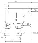
Found my power on latchup possibility. If the minus rail comes on first the input is tilted all the way to the negative side and the upper cascode collapses. The simple diode fixes this by powering the cascode if the input ever tilts all the way during turn on.
Good catch, as they say
Unobtainium components
The simplified Wurcer 990 I post in #1692 has excellent performance. On fas42's more stringent 100x 20kHz 20Vpp 600R test in #1694, its actually better than Guru Wurcer's more complex supa dupa circuit.
2nd -101.7dB 3rd -102.8dB Simplified 990
2nd -89.9dB 3rd -89.3dB Wurcer SupaDupa
But this is without the essential Clamping Diode Q8 It appears the evil non-linear leakage/capacitance of this diode is mucking things up big time.
If we could find a nice diode or diode-connected-BJT with very small leakage/capacitance, we could have Wurcer performance with much less complexity.
Any suggestions? Especially for diodes/BJTs with good SPICE models?
The voltage current requirements are quite small.
ricardo 'wannabe a SPICE guru' lee
While we're discussing Unobtainium components, I'll ask forum members for advice and move back on topic.You can still get c254x, Toshiba c3329 & Rohm d786 in qtys for small production but their pnp complements are truly Unobtainium.
The simplified Wurcer 990 I post in #1692 has excellent performance. On fas42's more stringent 100x 20kHz 20Vpp 600R test in #1694, its actually better than Guru Wurcer's more complex supa dupa circuit.
2nd -101.7dB 3rd -102.8dB Simplified 990
2nd -89.9dB 3rd -89.3dB Wurcer SupaDupa
But this is without the essential Clamping Diode Q8 It appears the evil non-linear leakage/capacitance of this diode is mucking things up big time.
If we could find a nice diode or diode-connected-BJT with very small leakage/capacitance, we could have Wurcer performance with much less complexity.
Any suggestions? Especially for diodes/BJTs with good SPICE models?
The voltage current requirements are quite small.
ricardo 'wannabe a SPICE guru' lee
Found my power on latchup possibility. If the minus rail comes on first the input is tilted all the way to the negative side and the upper cascode collapses. The simple diode fixes this by powering the cascode if the input ever tilts all the way during turn on.
Distortions due to the nonlinear diode capacitance?
Distortions due to the nonlinear diode capacitance?
No signal voltage across this point. Richard is talking about the JFET JE990 which has clamps that do see the signal. In IC's we had to use PNP's that had no reverse EB breakdown.
- Home
- Source & Line
- Analog Line Level
- Discrete Opamp Open Design